Ex17: 9+1-story SCBF, offset east core, torsionally irregular (gold) · generated 2026-07-15
This report is organised as the senior-engineer (EOR) acceptance checklist: one chapter per checklist section. Each chapter opens with the items a reviewer must accept, followed by the supporting analysis and design evidence. Appendix A is the fully-referenced AISC 360/341 member calc, Appendix B the member forces for every load case, Appendix C the activity log of the tool calls that produced the design.
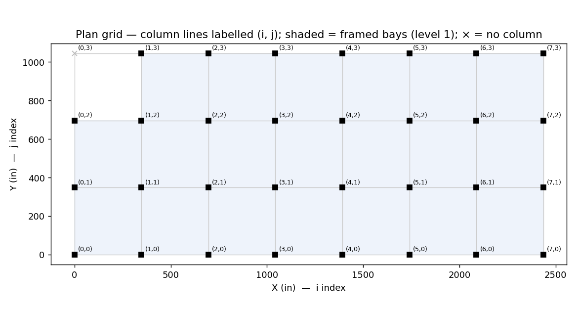
Model built to the parameters below — verify these against your brief, especially the bay count and spans.
| Parameter | Value |
|---|---|
| Lateral system | Ex17: 9+1-story SCBF, offset east core, torsionally irregular (gold) |
| Plan grid | 7 × 3 bays @ 29 × 29 ft (203 × 87 ft overall) |
| Stories | 10 @ 15, 12, 12, 12, 12, 12, 12, 12, 12, 12 ft (H = 127 ft) |
| Gravity loads | floor D 80.0 / L 65.0 psf; roof D 80.0 / L ? psf |
| Seismic | R=6.0, Cd=5.0, Ω0=2.0, Ie=1.0, SDS=1.0, S1=0.55 |
| Reference | Used for |
|---|---|
| International Building Code (IBC) | adopting code — confirm locally adopted edition & amendments |
| ASCE/SEI 7-22 | loads & load combinations (gravity, wind Ch.26-31, seismic Ch.11-12, §2.3 LRFD) |
| AISC 360-22 | steel member & connection design (LRFD) |
| AISC 341-22 | seismic provisions / ductile detailing & capacity design |
| AISC 358 | prequalified moment connections (if SMF/IMF used) |
| AWS D1.1 | structural welding |
| ACI 318 (Ch. 17) | cast-in anchorage at column bases |
| Parameter | Value |
|---|---|
| Risk Category | II |
| Importance factor Ie | 1.0 |
| SDS / SD1 | 1.0 / 0.55 g |
| Seismic Design Category | D (Tables 11.6-1/2; confirm E/F vs S1) |
| R / Cd / Ω0 | 6.0 / 5.0 / 2.0 |
| Redundancy ρ | 1.3 |
| Basic wind speed V | 110.0 mph, Exposure B |
This package covers the primary steel gravity and lateral framing, its members, and the analysis behind them. Connection design, foundations, cold-formed/joist framing, stairs, cladding attachment and embeds are delegated/deferred unless explicitly included; their demands are transmitted in Chapters 10-11. The reviewer should confirm the geotechnical and architectural criteria match this basis.
| Item | Value |
|---|---|
| Archetype | Ex17: 9+1-story SCBF, offset east core, torsionally irregular (gold) |
| Stories | 10 |
| Plan | 203 ft (X) × 87 ft (Y) |
| Bays | 7 × 3 @ 29 ft (X) / 29 ft (Y) |
| Height | 127 ft (hₙ) |
| Column bases | pinned |
| Lateral system | moment frame |
ASTM A992 steel: \(F_y=50\) ksi, \(F_u=65\) ksi, \(E=29{,}000\) ksi.
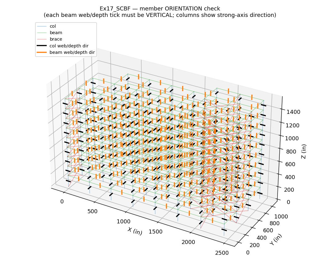
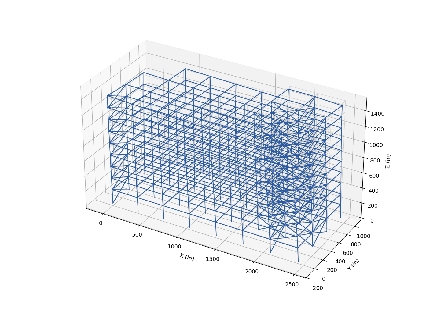
The lateral force-resisting system is a steel concentrically braced / dual in each principal direction. Gravity path: floor/roof pressure → floor beams (two-way tributary) → girders/columns → column bases → foundation. Lateral path: story inertial/wind force → rigid floor diaphragm → vertical lateral frames → column bases → foundation, in both orthogonal directions. The design inputs for each system are below; the horizontal distribution to the frames and the deformed shape that confirms the path are shown in this chapter and Chapter 5.
| Parameter | Value |
|---|---|
| Seismic force-resisting system (declared) | SCBF |
| Response modification R | 6.0 |
| Deflection amplification Cd | 5.0 |
| Overstrength Ω0 | 2.0 |
| Redundancy ρ | 1.3 (confirm vs §12.3.4.2; 1.0 if redundancy conditions met) |
| Structural height hn limit (Table 12.2-1) | 160 ft (SDC D/E), 100 ft (F) |
System is the one DECLARED in cfg['system']; apply its AISC 341 provisions in Chapter 9 and confirm the Table 12.2-1 height limit for the SDC. Use the same system both directions unless cfg declares a different system per direction.
| Lateral-load input | Value |
|---|---|
| Seismic SDS / SD1 | 1.0 / 0.55 g |
| R / Cd / Ω0 / Ie | 6.0 / 5.0 / 2.0 / 1.0 |
| Period coeff Ct / x / Cu | 0.02 / 0.75 / 1.4 |
| Wind V / Exposure | 110.0 mph / B |
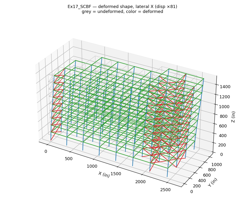
View model interactive 3D viewer (geometry, mode shapes, loads, member D∕C) — opens in a new tab
The story shear in each direction is shared by the two parallel lateral frames. The governing base shear (greater of wind and seismic) is split about 50/50 to each frame, plus ±5% accidental torsion (ASCE 7-22 §12.8.4.2) which biases demand toward the leading frame.
| Direction / frames | Wind base (kip) | Seismic base (kip) | Governs | Per frame (kip) |
|---|---|---|---|---|
| E-W — two moment frames | 254 | 1209 | seismic | 605 |
| N-S — two braced frames | 566 | 1209 | seismic | 605 |
The floor/roof is taken as a rigid diaphragm (concrete-filled metal deck), distributing story forces to the lateral frames in proportion to their stiffness and modelled with a rigid in-plane constraint per ASCE 7-22 §12.3.1.2. Collectors/drag struts carry the diaphragm shear into the frames; chord forces (Mdiaph/depth) are resisted by the perimeter beams. The diaphragm, its collectors and chords are designed for the force Fpx below (§12.10.1.1).
| Level x | wpx (kip) | Fpx Eq.12.10-1 (kip) | min 0.2SDSIewpx | max 0.4SDSIewpx | Fpx design (kip) |
|---|---|---|---|---|---|
| 1 | 1502 | 130 | 300 | 601 | 300 (min) |
| 2 | 1476 | 141 | 295 | 590 | 295 (min) |
| 3 | 1476 | 155 | 295 | 590 | 295 (min) |
| 4 | 1476 | 169 | 295 | 590 | 295 (min) |
| 5 | 1476 | 184 | 295 | 590 | 295 (min) |
| 6 | 1476 | 200 | 295 | 590 | 295 (min) |
| 7 | 1476 | 215 | 295 | 590 | 295 (min) |
| 8 | 1476 | 232 | 295 | 590 | 295 (min) |
| 9 | 1476 | 250 | 295 | 590 | 295 (min) |
| 10 | 662 | 122 | 132 | 265 | 132 (min) |
Fpx is the diaphragm/collector design force; the detailed diaphragm, collector and chord design is delegated and confirmed on the drawings.
Screening against ASCE 7-22 Tables 12.3-1 (plan) and 12.3-2 (vertical). The torsional ratio is the story diaphragm displacement-ratio under the ±5% accidental eccentricity (rigid-diaphragm estimate); ≥1.2 triggers a torsional irregularity and amplification Ax (§12.8.4.3).
| Irregularity type | Determination |
|---|---|
| Horizontal 1a/1b — Torsional / extreme | Torsional (1a): ratio 1.23 ≥ 1.2 — apply Ax = 1.04 (§12.8.4.3) |
| Horizontal 2 — Re-entrant corners | Type 2 RE-ENTRANT: YES — non-convex footprint. Requires MODAL RESPONSE SPECTRUM (12.6/12.9) and a 25% increase to diaphragm-to-collector CONNECTION forces (§12.3.3.4), with Ω0 collectors on the re-entrant grid lines. |
| Horizontal 3 — Diaphragm discontinuity | None (solid rigid diaphragm; confirm any large openings/atria) |
| Horizontal 4 — Out-of-plane offset | None (continuous vertical frames; confirm no transfer) |
| Horizontal 5 — Nonparallel system | None (orthogonal frames) |
| Vertical 1a/1b — Soft / extreme soft story | Check stiffness/soft-story: tallest/shortest story height ratio 1.20 |
| Vertical 2 — Mass (weight) | Mass irregularity (Vert-2): adjacent ratio 2.23 > 1.5 |
| Vertical 3 — Geometric (setback) | Type 3 GEOMETRIC SETBACK: YES — footprint reduces with height; design the transfer/backstay diaphragm at the setback with Ω0 collectors. |
| Vertical 4 — In-plane discontinuity | None (aligned frames; confirm no transfer columns) |
| Vertical 5a/5b — Weak / extreme weak story | Confirm against story shear strengths (Ch 6/9) |
| Gravity load | Value |
|---|---|
| Floor dead, D | 80.0 psf |
| Roof dead, D | 80.0 psf |
| Cladding | 18.0 psf of wall |
| Floor live, L | 65.0 psf |
| Roof live, Lr | 20.0 psf |
Dead D is the bundled member self-weight + superimposed dead (MEP, ceilings, finishes, partition allowance) plus façade cladding — itemise on the load schedule. Live L is applied at full L0 (no §4.7 reduction taken — conservative); L = L0(0.25 + 15/√(KLLAT)) may be used in member design where KLLAT ≥ 400 ft² and reduction is permitted. Roof carries a uniform Lr/snow; flat-roof snow, drift, unbalanced/sliding snow, rain-on-snow and ponding stability are confirmed separately (out of scope for the uniform roof model).
ASCE 7-22 §27 MWFRS. Velocity pressure qz = 0.00256·Kz·Kzt·Kd·V²; design pressure p = qz·G·Cpnet; story force = p × tributary width × tributary height.
| Parameter | Value |
|---|---|
| Basic wind speed V | 110.0 mph |
| Exposure | B |
| Kd / G / Cpnet | 0.85 / 0.85 / 1.3 |
Story wind forces (kip):
| Story | X (E-W wind) | Y (N-S wind) |
|---|---|---|
| 1 | 21.8 | 50.9 |
| 2 | 20.1 | 46.9 |
| 3 | 22.9 | 53.5 |
| 4 | 25.1 | 58.5 |
| 5 | 26.9 | 62.7 |
| 6 | 28.4 | 66.2 |
| 7 | 29.7 | 69.4 |
| 8 | 30.9 | 72.2 |
| 9 | 32.0 | 74.7 |
| 10 | 15.8 | 10.6 |
Wind base shear: X = 254 kip, Y = 566 kip.
The forces above are the MWFRS (main wind force-resisting system) for the overall building (windward + leeward combined via Cp,net). Components & cladding (C&C) pressures — zone GCp of §30 for cladding, fasteners and their supports — and across-wind/torsional MWFRS load cases are part of the (delegated) cladding design.
ASCE 7-22 §12.8 equivalent lateral force. Seismic weight W = 13973 kip; SDS = 1.0 g, SD1 = 0.55 g, S1 = 0.55 g, R = 6.0, Ie = 1.0. Approximate period Ta = Cthnx = 0.76 s; design period T = min(Tcomputed, CuTa) = 1.06 s (§12.8.2).
| Cs equation | Value |
|---|---|
| Cs = SDS/(R/Ie) (Eq.12.8-2) | 0.1667 |
| Cs,max = SD1/(T·R/Ie) (Eq.12.8-3) | 0.0865 |
| Cs,min = max(0.044·SDSIe, 0.01) (Eq.12.8-5) | 0.0440 |
| Governing Cs | 0.0865 (Cs,max (Eq.12.8-3)) |
Design base shear V = CsW = 0.0865 × 13973 = 1209 kip in each direction.
Fx = CvxV, Cvx = wxhxk / Σ wihik.
| Floor | w (kip) | h (ft) | w·hk | Cvx | Fx (kip) |
|---|---|---|---|---|---|
| 1 | 1502 | 15.0 | 48,051 | 0.015 | 18.0 |
| 2 | 1476 | 27.5 | 102,552 | 0.032 | 38.4 |
| 3 | 1476 | 40.0 | 165,644 | 0.051 | 62.0 |
| 4 | 1476 | 52.5 | 234,585 | 0.073 | 87.8 |
| 5 | 1476 | 65.0 | 308,313 | 0.095 | 115.4 |
| 6 | 1476 | 77.5 | 386,137 | 0.120 | 144.5 |
| 7 | 1476 | 90.0 | 467,566 | 0.145 | 175.0 |
| 8 | 1476 | 102.5 | 552,228 | 0.171 | 206.7 |
| 9 | 1476 | 115.0 | 639,834 | 0.198 | 239.5 |
| 10 | 662 | 127.0 | 325,848 | 0.101 | 122.0 |
| Mode | T (s) | mX % | ΣmX % | mY % | ΣmY % |
|---|---|---|---|---|---|
| 1 | 1.063 | 0.9 | 0.9 | 50.2 | 50.2 |
| 2 | 1.034 | 68.1 | 69.0 | 4.6 | 54.8 |
| 3 | 0.734 | 7.4 | 76.4 | 19.9 | 74.7 |
| 4 | 0.347 | 3.1 | 79.5 | 7.9 | 82.6 |
| 5 | 0.338 | 12.5 | 92.0 | 4.3 | 86.9 |
| 6 | 0.263 | 0.1 | 92.1 | 2.3 | 89.2 |
| 7 | 0.241 | 0.3 | 92.4 | 2.9 | 92.2 |
| 8 | 0.197 | 3.6 | 96.0 | 0.0 | 92.2 |
| 9 | 0.187 | 0.1 | 96.1 | 3.0 | 95.2 |
| 10 | 0.140 | 0.5 | 96.6 | 0.3 | 95.5 |
| 11 | 0.139 | 1.2 | 97.7 | 0.3 | 95.8 |
| 12 | 0.131 | 0.0 | 97.7 | 1.7 | 97.6 |
Mode-shape figures are in Chapter 5. Vertical seismic Ev = 0.2·SDSD, redundancy ρ, the 100/30 directional combination and ±5% accidental torsion are applied in the load combinations (Chapter 4); torsional amplification is screened in Chapter 2.
| Direction | Seismic V (kip) | Wind V (kip) | Governs |
|---|---|---|---|
| X (E-W) | 1209 | 254 | Seismic |
| Y (N-S) | 1209 | 566 | Seismic |
Strength-level base-shear comparison (seismic E and wind W are both strength-level in ASCE 7-22 LRFD). The governing system per direction sizes the lateral frames; both are carried through the load combinations (Chapter 4).
The analysed set is the ASCE 7-22 §2.3 LRFD strength combinations:
| Combination | D | L | Lr/S | Lateral | Applies to |
|---|---|---|---|---|---|
| 1.4D | 1.40 | 0.00 | 0.00 | — | all members |
| 1.2D+1.6L+0.5Lr | 1.20 | 1.60 | 0.50 | — | all members |
| 1.2D+1.6Lr+0.5L | 1.20 | 0.50 | 1.60 | — | all members |
| (1.2+0.2SDS)D+rhoEX+t++L+0.2S | 1.40 | 0.50 | 0.00 | seismic | all members |
| (0.9-0.2SDS)D+rhoEX+t+ | 0.70 | 0.00 | 0.00 | seismic | all members |
| (1.2+0.2SDS)D+rhoEX+t-+L+0.2S | 1.40 | 0.50 | 0.00 | seismic | all members |
| (0.9-0.2SDS)D+rhoEX+t- | 0.70 | 0.00 | 0.00 | seismic | all members |
| (1.2+0.2SDS)D+rhoEX-t++L+0.2S | 1.40 | 0.50 | 0.00 | seismic | all members |
| (0.9-0.2SDS)D+rhoEX-t+ | 0.70 | 0.00 | 0.00 | seismic | all members |
| (1.2+0.2SDS)D+rhoEX-t-+L+0.2S | 1.40 | 0.50 | 0.00 | seismic | all members |
| (0.9-0.2SDS)D+rhoEX-t- | 0.70 | 0.00 | 0.00 | seismic | all members |
| (1.2+0.2SDS)D+rhoEY+t++L+0.2S | 1.40 | 0.50 | 0.00 | seismic | all members |
| (0.9-0.2SDS)D+rhoEY+t+ | 0.70 | 0.00 | 0.00 | seismic | all members |
| (1.2+0.2SDS)D+rhoEY+t-+L+0.2S | 1.40 | 0.50 | 0.00 | seismic | all members |
| (0.9-0.2SDS)D+rhoEY+t- | 0.70 | 0.00 | 0.00 | seismic | all members |
| (1.2+0.2SDS)D+rhoEY-t++L+0.2S | 1.40 | 0.50 | 0.00 | seismic | all members |
| (0.9-0.2SDS)D+rhoEY-t+ | 0.70 | 0.00 | 0.00 | seismic | all members |
| (1.2+0.2SDS)D+rhoEY-t-+L+0.2S | 1.40 | 0.50 | 0.00 | seismic | all members |
| (0.9-0.2SDS)D+rhoEY-t- | 0.70 | 0.00 | 0.00 | seismic | all members |
| (1.2+0.2SDS)D+Om0*EX++L+0.2S [col] | 1.40 | 0.50 | 0.00 | seismic | columns only |
| (0.9-0.2SDS)D+Om0*EX+ [col] | 0.70 | 0.00 | 0.00 | seismic | columns only |
| (1.2+0.2SDS)D+Om0*EX-+L+0.2S [col] | 1.40 | 0.50 | 0.00 | seismic | columns only |
| (0.9-0.2SDS)D+Om0*EX- [col] | 0.70 | 0.00 | 0.00 | seismic | columns only |
| (1.2+0.2SDS)D+Om0*EY++L+0.2S [col] | 1.40 | 0.50 | 0.00 | seismic | columns only |
| (0.9-0.2SDS)D+Om0*EY+ [col] | 0.70 | 0.00 | 0.00 | seismic | columns only |
| (1.2+0.2SDS)D+Om0*EY-+L+0.2S [col] | 1.40 | 0.50 | 0.00 | seismic | columns only |
| (0.9-0.2SDS)D+Om0*EY- [col] | 0.70 | 0.00 | 0.00 | seismic | columns only |
| 1.2D+1.0WX++L+0.5Lr | 1.20 | 0.50 | 0.50 | wind | all members |
| 0.9D+1.0WX+ | 0.90 | 0.00 | 0.00 | wind | all members |
| 1.2D+1.0WX-+L+0.5Lr | 1.20 | 0.50 | 0.50 | wind | all members |
| 0.9D+1.0WX- | 0.90 | 0.00 | 0.00 | wind | all members |
| 1.2D+1.0WY++L+0.5Lr | 1.20 | 0.50 | 0.50 | wind | all members |
| 0.9D+1.0WY+ | 0.90 | 0.00 | 0.00 | wind | all members |
| 1.2D+1.0WY-+L+0.5Lr | 1.20 | 0.50 | 0.50 | wind | all members |
| 0.9D+1.0WY- | 0.90 | 0.00 | 0.00 | wind | all members |
| Symbol | Meaning |
|---|---|
| D | dead load |
| L | floor live load (reducible per ASCE 7-22 §4.7) |
| Lr / S | roof live load / snow |
| EX, EY | horizontal seismic effect QE (ELF) in the X (E-W) / Y (N-S) direction; the vertical term Ev=0.2SDSD is folded into the D factor |
| WX, WY | wind load in the X / Y direction |
| ρ | redundancy factor multiplying QE (§12.3.4); ρ=1.0 here (SDC B) |
| Ω0 | overstrength factor; the “[col]” cases apply Ω0QE to capacity-protected columns only (§12.4.3) |
| t+ / t− | ±5% accidental torsion Mt = ±0.05B·Fx (§12.8.4.2) |
| + / − | sign (direction) of the applied lateral load |
| [col] | combination applied to columns only |
| 0.5L, 0.2S, 0.9D | companion / counteracting load factors (ASCE 7-22 §2.3) |
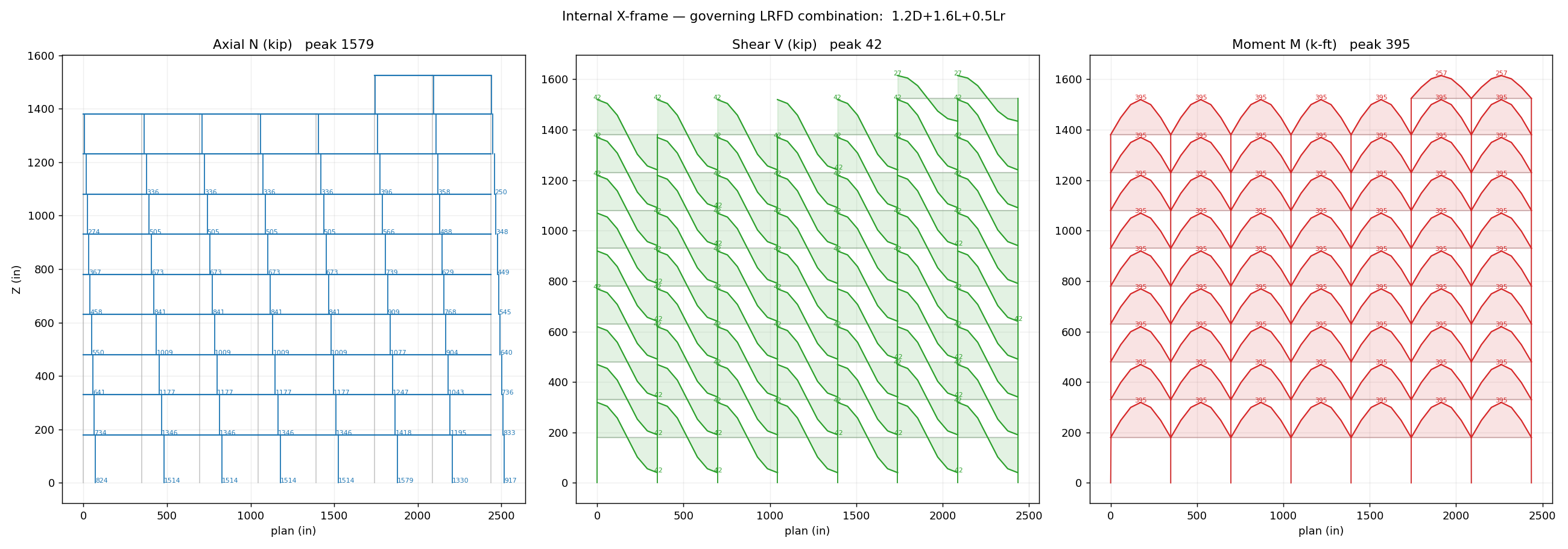
One row per combination: the largest axial force and the largest bending moment anywhere in the structure, with the member type/section that carries it (from the static model, so gravity beam moments are correct). The governing N/V/M diagrams are in Chapter 5 (cfg['force_diagrams']); the per-combination N/V/M figures are in Appendix B (cfg['appendix_case_figures']).
| Load case | Max axial N (kip) | carried by | Max moment M (k-ft) | carried by |
|---|---|---|---|---|
| 1.4D | 915 | col W14X605 | 277 | beam W36X160 |
| 1.2D+1.6L+0.5Lr | 1579 | col W14X605 | 395 | beam W36X160 |
| 1.2D+1.6Lr+0.5L | 1046 | col W14X605 | 300 | beam W24X62 |
| (1.2+0.2SDS)D+rhoEX+t++L+0.2S | 2014 | col W14X605 | 286 | beam W36X160 |
| (0.9-0.2SDS)D+rhoEX+t+ | 1508 | col W14X605 | 138 | beam W36X160 |
| (1.2+0.2SDS)D+rhoEX+t-+L+0.2S | 2088 | col W14X605 | 286 | beam W36X160 |
| (0.9-0.2SDS)D+rhoEX+t- | 1576 | col W14X605 | 138 | beam W36X160 |
| (1.2+0.2SDS)D+rhoEX-t++L+0.2S | 2669 | col W14X605 | 286 | beam W36X160 |
| (0.9-0.2SDS)D+rhoEX-t+ | 1949 | col W14X605 | 138 | beam W36X160 |
| (1.2+0.2SDS)D+rhoEX-t-+L+0.2S | 2668 | col W14X605 | 286 | beam W36X160 |
| (0.9-0.2SDS)D+rhoEX-t- | 1949 | col W14X605 | 138 | beam W36X160 |
| (1.2+0.2SDS)D+rhoEY+t++L+0.2S | 2059 | col W14X605 | 286 | beam W24X76 |
| (0.9-0.2SDS)D+rhoEY+t+ | 1667 | col W14X605 | 138 | beam W36X160 |
| (1.2+0.2SDS)D+rhoEY+t-+L+0.2S | 2524 | col W14X605 | 286 | beam W36X160 |
| (0.9-0.2SDS)D+rhoEY+t- | 2128 | col W14X605 | 138 | beam W36X160 |
| (1.2+0.2SDS)D+rhoEY-t++L+0.2S | 1826 | col W14X605 | 286 | beam W36X160 |
| (0.9-0.2SDS)D+rhoEY-t+ | 1559 | col W14X605 | 138 | beam W36X160 |
| (1.2+0.2SDS)D+rhoEY-t-+L+0.2S | 2246 | col W14X605 | 286 | beam W24X76 |
| (0.9-0.2SDS)D+rhoEY-t- | 2020 | col W14X605 | 138 | beam W36X160 |
| (1.2+0.2SDS)D+Om0*EX++L+0.2S [col] | — | Ω0 column overstrength (see Ch. 6) | — | |
| (0.9-0.2SDS)D+Om0*EX+ [col] | — | Ω0 column overstrength (see Ch. 6) | — | |
| (1.2+0.2SDS)D+Om0*EX-+L+0.2S [col] | — | Ω0 column overstrength (see Ch. 6) | — | |
| (0.9-0.2SDS)D+Om0*EX- [col] | — | Ω0 column overstrength (see Ch. 6) | — | |
| (1.2+0.2SDS)D+Om0*EY++L+0.2S [col] | — | Ω0 column overstrength (see Ch. 6) | — | |
| (0.9-0.2SDS)D+Om0*EY+ [col] | — | Ω0 column overstrength (see Ch. 6) | — | |
| (1.2+0.2SDS)D+Om0*EY-+L+0.2S [col] | — | Ω0 column overstrength (see Ch. 6) | — | |
| (0.9-0.2SDS)D+Om0*EY- [col] | — | Ω0 column overstrength (see Ch. 6) | — | |
| 1.2D+1.0WX++L+0.5Lr | 1093 | col W14X605 | 257 | beam W24X62 |
| 0.9D+1.0WX+ | 698 | col W14X605 | 178 | beam W36X160 |
| 1.2D+1.0WX-+L+0.5Lr | 1245 | col W14X605 | 257 | beam W36X160 |
| 0.9D+1.0WX- | 796 | col W14X605 | 178 | beam W36X160 |
| 1.2D+1.0WY++L+0.5Lr | 1122 | col W14X605 | 257 | beam W36X160 |
| 0.9D+1.0WY+ | 828 | col W14X605 | 178 | beam W36X160 |
| 1.2D+1.0WY-+L+0.5Lr | 1131 | col W14X605 | 257 | beam W36X160 |
| 0.9D+1.0WY- | 736 | col W14X605 | 178 | beam W36X160 |
| Assumption | As modelled |
|---|---|
| Column bases | pinned |
| Beam-column & brace joints | custom (defined in custom_build) |
| Floor diaphragm | rigid (in-plane), masters at floor centroid |
| Geometric transform | P-Δ (second-order) on columns |
| Leaning gravity columns | framed into the lateral system |
| Gravity for member forces | static model — true two-way (45°) tributary line loads on sub-divided beams |
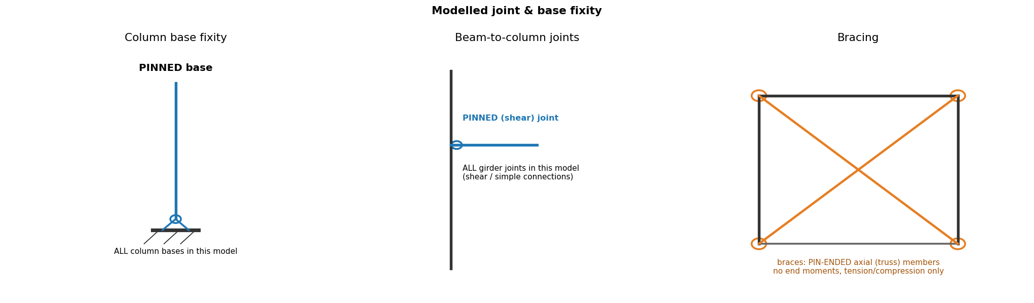
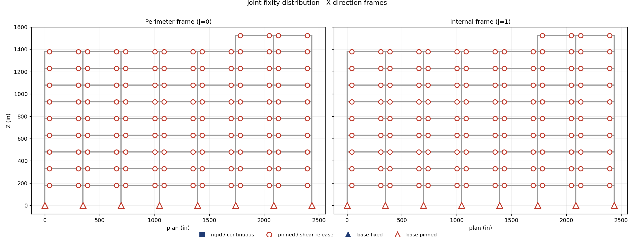
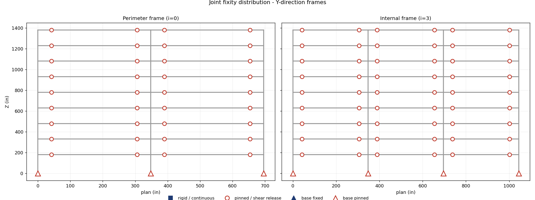
Analysis basis: a second-order P-Δ geometric transformation is applied to the columns under every factored combination (no superposition of factored results). Effective length K = 1 is used, consistent with a second-order analysis. If the Direct Analysis Method (AISC 360-22 §C2) is the design basis, the 0.8·EI / 0.8τb·EA stiffness reductions and notional loads Ni = 0.002αYi are confirmed at the member-design stage; the story stability coefficient θ (§12.8.7) and the B2 amplifier are reported in Chapter 7.
|ΣRx| = 1209 kip vs applied base shear 1209 kip (equal and opposite); ΣRz = 24725 kip factored gravity delivered to the ground. Reactions balance the applied loads in all three axes (load path verified).
Modal mass participation: ΣmX = 99% (OK), ΣmY = 99% (OK); ASCE 7-22 §12.9.1 requires ≥ 90% in each direction. Periods and mode shapes are shown below and in Chapter 3.
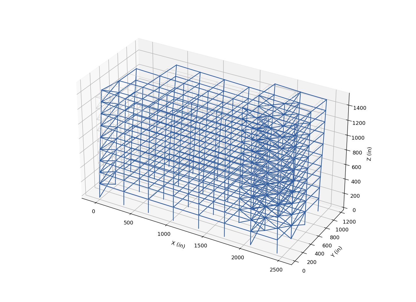
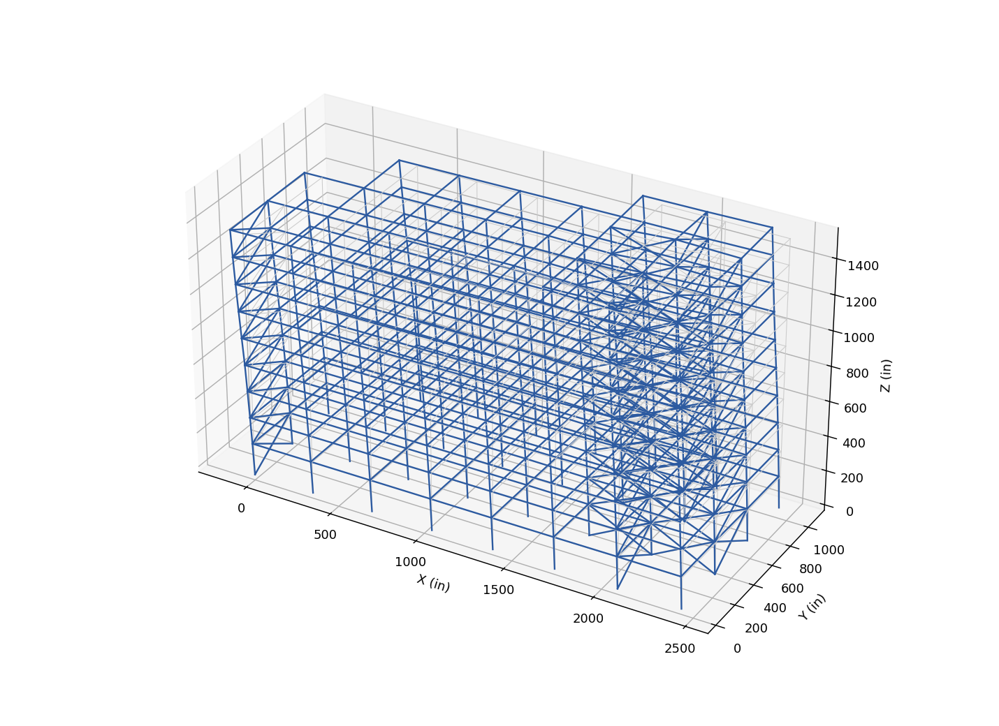
Animated mode-shape videos (modes 1–3) temporarily omitted for faster reporting — can be populated here on request at the completion of the design.
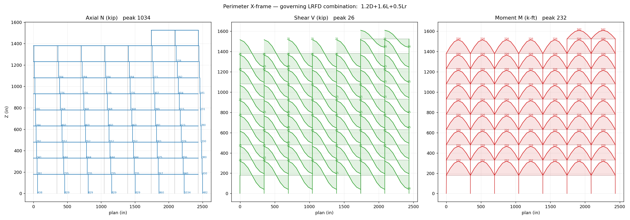
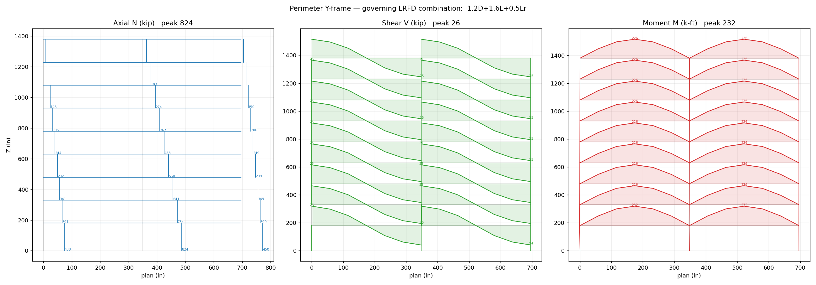
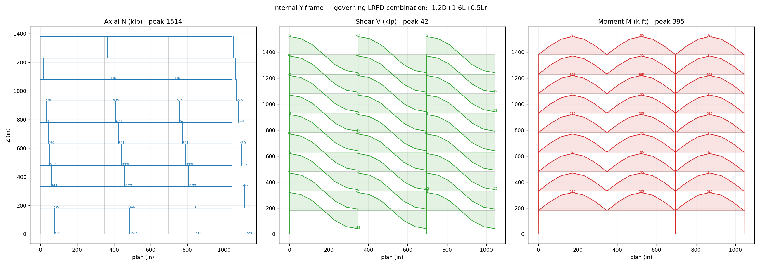
N / V / M for each perimeter frame under its governing LRFD combination, from the static model (true two-way tributary loads on sub-divided beams). Peak values annotated per member; columns are single elements (linear between ends).
The same diagrams for an interior frame line, which generally carries more gravity tributary (and less lateral) than the perimeter — the gravity-governed companion check.
Roof beams/girders for roof dead + roof live (and snow); governing flexure/shear/deflection limit state.
Section properties / geometry (AISC Shapes Database v16):
| A (in2) | Zx (in3) | Sx (in3) | Zy (in3) | Sy (in3) | rx (in) | ry (in) | Aw (in2) | J (in4) | L (in) | Lb (in) |
|---|---|---|---|---|---|---|---|---|---|---|
| 18.2 | 153.0 | 131.0 | 15.7 | 9.8 | 9.23 | 1.38 | 10.19 | 1.71 | 348.0 | 76.0 |
Demand envelope (analysis):
| P_comp (kip) | P_tens (kip) | Mz (kip-in) | My (kip-in) | V (kip) | governing combo |
|---|---|---|---|---|---|
| 0.0 | 0.0 | 4682.7 | 0.0 | 53.82 | 1.2D+1.6Lr+0.5L |
| Quantity | Calculation | Value | Ref. (AISC) |
|---|---|---|---|
| Governing limit state | selected from AISC 360 | flexure (LTB/FLB) + shear | AISC 360-22 F2 (F2-2 (inelastic LTB)), phi_b=0.90 (F1); flange compact (Table B4.1b); AISC 360-22 G2.1(a): Vn=0.6FyAwCv1 (G2-1), Cv1=1.0, phi_v=1.00 |
| phiMn_kipin | 5502.0 | ||
| phiVn_kip | 305.7 | ||
| Lb_in | 116.0 | ||
| Cb | 1.0 | ||
| D/C | demand / capacity | 0.851 ok | AISC 360-22 F2 (F2-2 (inelastic LTB)), phi_b=0.90 (F1); flange compact (Table B4.1b); AISC 360-22 G2.1(a): Vn=0.6FyAwCv1 (G2-1), Cv1=1.0, phi_v=1.00 |
Section properties / geometry (AISC Shapes Database v16):
| A (in2) | Zx (in3) | Sx (in3) | Zy (in3) | Sy (in3) | rx (in) | ry (in) | Aw (in2) | J (in4) | L (in) | Lb (in) |
|---|---|---|---|---|---|---|---|---|---|---|
| 47.0 | 624.0 | 542.0 | 77.3 | 49.1 | 14.4 | 2.5 | 23.4 | 12.4 | 348.0 | 137.8 |
Demand envelope (analysis):
| P_comp (kip) | P_tens (kip) | Mz (kip-in) | My (kip-in) | V (kip) | governing combo |
|---|---|---|---|---|---|
| 0.0 | 0.0 | 21148.514800537523 | 0.0 | 53.82 | 1.2D+1.6Lr+0.5L |
| Quantity | Calculation | Value | Ref. (AISC) |
|---|---|---|---|
| Governing limit state | selected from AISC 360 | flexure (LTB/FLB) + shear | AISC 360-22 F2 (F2-2 (inelastic LTB)), phi_b=0.90 (F1); flange compact (Table B4.1b); AISC 360-22 G2.1(a): Vn=0.6FyAwCv1 (G2-1), Cv1=1.0, phi_v=1.00; braced-bay intermediate beam includes two-story-X unbalanced force (T-0.3C)sin(theta) per AISC 341-22 F2.3 analysis (b) |
| phiMn_kipin | 27539.0 | ||
| phiVn_kip | 702.0 | ||
| Lb_in | 116.0 | ||
| Cb | 1.0 | ||
| D/C | demand / capacity | 0.768 ok | AISC 360-22 F2 (F2-2 (inelastic LTB)), phi_b=0.90 (F1); flange compact (Table B4.1b); AISC 360-22 G2.1(a): Vn=0.6FyAwCv1 (G2-1), Cv1=1.0, phi_v=1.00; braced-bay intermediate beam includes two-story-X unbalanced force (T-0.3C)sin(theta) per AISC 341-22 F2.3 analysis (b) |
Typical floor beams/girders for floor dead + live load.
Section properties / geometry (AISC Shapes Database v16):
| A (in2) | Zx (in3) | Sx (in3) | Zy (in3) | Sy (in3) | rx (in) | ry (in) | Aw (in2) | J (in4) | L (in) | Lb (in) |
|---|---|---|---|---|---|---|---|---|---|---|
| 22.4 | 200.0 | 176.0 | 28.6 | 18.4 | 9.69 | 1.92 | 10.52 | 2.68 | 348.0 | 105.8 |
Demand envelope (analysis):
| P_comp (kip) | P_tens (kip) | Mz (kip-in) | My (kip-in) | V (kip) | governing combo |
|---|---|---|---|---|---|
| 0.0 | 0.0 | 7316.7 | 0.0 | 84.1 | 1.2D+1.6L+0.5Lr |
| Quantity | Calculation | Value | Ref. (AISC) |
|---|---|---|---|
| Governing limit state | selected from AISC 360 | flexure (LTB/FLB) + shear | AISC 360-22 F2 (F2-2 (inelastic LTB)), phi_b=0.90 (F1); flange compact (Table B4.1b); AISC 360-22 G2.1(a): Vn=0.6FyAwCv1 (G2-1), Cv1=1.0, phi_v=1.00 |
| phiMn_kipin | 8216.0 | ||
| phiVn_kip | 315.5 | ||
| Lb_in | 116.0 | ||
| Cb | 1.0 | ||
| D/C | demand / capacity | 0.891 ok | AISC 360-22 F2 (F2-2 (inelastic LTB)), phi_b=0.90 (F1); flange compact (Table B4.1b); AISC 360-22 G2.1(a): Vn=0.6FyAwCv1 (G2-1), Cv1=1.0, phi_v=1.00 |
Section properties / geometry (AISC Shapes Database v16):
| A (in2) | Zx (in3) | Sx (in3) | Zy (in3) | Sy (in3) | rx (in) | ry (in) | Aw (in2) | J (in4) | L (in) | Lb (in) |
|---|---|---|---|---|---|---|---|---|---|---|
| 47.0 | 624.0 | 542.0 | 77.3 | 49.1 | 14.4 | 2.5 | 23.4 | 12.4 | 348.0 | 137.8 |
Demand envelope (analysis):
| P_comp (kip) | P_tens (kip) | Mz (kip-in) | My (kip-in) | V (kip) | governing combo |
|---|---|---|---|---|---|
| 0.0 | 0.0 | 23782.514800537523 | 0.0 | 84.1 | 1.2D+1.6L+0.5Lr |
| Quantity | Calculation | Value | Ref. (AISC) |
|---|---|---|---|
| Governing limit state | selected from AISC 360 | flexure (LTB/FLB) + shear | AISC 360-22 F2 (F2-2 (inelastic LTB)), phi_b=0.90 (F1); flange compact (Table B4.1b); AISC 360-22 G2.1(a): Vn=0.6FyAwCv1 (G2-1), Cv1=1.0, phi_v=1.00; braced-bay intermediate beam includes two-story-X unbalanced force (T-0.3C)sin(theta) per AISC 341-22 F2.3 analysis (b) |
| phiMn_kipin | 27539.0 | ||
| phiVn_kip | 702.0 | ||
| Lb_in | 116.0 | ||
| Cb | 1.0 | ||
| D/C | demand / capacity | 0.864 ok | AISC 360-22 F2 (F2-2 (inelastic LTB)), phi_b=0.90 (F1); flange compact (Table B4.1b); AISC 360-22 G2.1(a): Vn=0.6FyAwCv1 (G2-1), Cv1=1.0, phi_v=1.00; braced-bay intermediate beam includes two-story-X unbalanced force (T-0.3C)sin(theta) per AISC 341-22 F2.3 analysis (b) |
Interior gravity columns for accumulated tributary gravity (AISC 360 §E3 compression).
Section properties / geometry (AISC Shapes Database v16):
| A (in2) | Zx (in3) | Sx (in3) | Zy (in3) | Sy (in3) | rx (in) | ry (in) | Aw (in2) | J (in4) | L (in) | Lb (in) |
|---|---|---|---|---|---|---|---|---|---|---|
| 32.0 | 192.0 | 173.0 | 92.7 | 61.2 | 6.22 | 3.73 | 7.51 | 7.12 | 150.0 | 150.0 |
Demand envelope (analysis):
| P_comp (kip) | P_tens (kip) | Mz (kip-in) | My (kip-in) | V (kip) | governing combo |
|---|---|---|---|---|---|
| 1177.4 | 0.0 | 267.6 | 89.7 | 1.89 | 1.2D+1.6L+0.5Lr |
| Quantity | Calculation | Value | Ref. (AISC) |
|---|---|---|---|
| Governing limit state | selected from AISC 360 | compression E3 + interaction H1-1a | AISC 360-22 E3 (Eqs. E3-1, E3-2, E3-4), phi_c=0.90 (E1); AISC 360-22 F2 (F2-1 (Lb<=Lp: LTB does not apply)), phi_b=0.90 (F1); flange compact (Table B4.1b); AISC 360-22 H1.1 Eq. H1-1a |
| phiPn_kip | 1279.0 | ||
| phiMnx_kipin | 8640.0 | ||
| phiMny_kipin | 4172.0 | ||
| Lc_in | 150.0 | ||
| D/C | demand / capacity | 0.967 ok | AISC 360-22 E3 (Eqs. E3-1, E3-2, E3-4), phi_c=0.90 (E1); AISC 360-22 F2 (F2-1 (Lb<=Lp: LTB does not apply)), phi_b=0.90 (F1); flange compact (Table B4.1b); AISC 360-22 H1.1 Eq. H1-1a |
Section properties / geometry (AISC Shapes Database v16):
| A (in2) | Zx (in3) | Sx (in3) | Zy (in3) | Sy (in3) | rx (in) | ry (in) | Aw (in2) | J (in4) | L (in) | Lb (in) |
|---|---|---|---|---|---|---|---|---|---|---|
| 42.7 | 260.0 | 232.0 | 133.0 | 87.3 | 6.33 | 3.98 | 10.06 | 15.2 | 180.0 | 180.0 |
Demand envelope (analysis):
| P_comp (kip) | P_tens (kip) | Mz (kip-in) | My (kip-in) | V (kip) | governing combo |
|---|---|---|---|---|---|
| 1513.8 | 0.0 | 211.8 | 76.3 | 1.97 | 1.2D+1.6L+0.5Lr |
| Quantity | Calculation | Value | Ref. (AISC) |
|---|---|---|---|
| Governing limit state | selected from AISC 360 | compression E3 + interaction H1-1a | AISC 360-22 E3 (Eqs. E3-1, E3-2, E3-4), phi_c=0.90 (E1); AISC 360-22 F2 (F2-2 (inelastic LTB)), phi_b=0.90 (F1); flange compact (Table B4.1b); AISC 360-22 H1.1 Eq. H1-1a |
| phiPn_kip | 1655.0 | ||
| phiMnx_kipin | 11613.0 | ||
| phiMny_kipin | 5985.0 | ||
| Lc_in | 180.0 | ||
| D/C | demand / capacity | 0.942 ok | AISC 360-22 E3 (Eqs. E3-1, E3-2, E3-4), phi_c=0.90 (E1); AISC 360-22 F2 (F2-2 (inelastic LTB)), phi_b=0.90 (F1); flange compact (Table B4.1b); AISC 360-22 H1.1 Eq. H1-1a |
Section properties / geometry (AISC Shapes Database v16):
| A (in2) | Zx (in3) | Sx (in3) | Zy (in3) | Sy (in3) | rx (in) | ry (in) | Aw (in2) | J (in4) | L (in) | Lb (in) |
|---|---|---|---|---|---|---|---|---|---|---|
| 14.1 | 78.4 | 70.2 | 19.6 | 12.8 | 5.85 | 1.91 | 4.69 | 1.45 | 150.0 | 150.0 |
Demand envelope (analysis):
| P_comp (kip) | P_tens (kip) | Mz (kip-in) | My (kip-in) | V (kip) | governing combo |
|---|---|---|---|---|---|
| 168.2 | 0.0 | 113.1 | 12.0 | 0.79 | 1.2D+1.6L+0.5Lr |
| Quantity | Calculation | Value | Ref. (AISC) |
|---|---|---|---|
| Governing limit state | selected from AISC 360 | compression E3 + interaction H1-1a | AISC 360-22 E3 (Eqs. E3-1, E3-2, E3-4), phi_c=0.90 (E1); AISC 360-22 F2 (F2-2 (inelastic LTB)), phi_b=0.90 (F1); flange compact (Table B4.1b); AISC 360-22 H1.1 Eq. H1-1a |
| phiPn_kip | 404.0 | ||
| phiMnx_kipin | 3000.0 | ||
| phiMny_kipin | 882.0 | ||
| Lc_in | 150.0 | ||
| D/C | demand / capacity | 0.462 ok | AISC 360-22 E3 (Eqs. E3-1, E3-2, E3-4), phi_c=0.90 (E1); AISC 360-22 F2 (F2-2 (inelastic LTB)), phi_b=0.90 (F1); flange compact (Table B4.1b); AISC 360-22 H1.1 Eq. H1-1a |
Section properties / geometry (AISC Shapes Database v16):
| A (in2) | Zx (in3) | Sx (in3) | Zy (in3) | Sy (in3) | rx (in) | ry (in) | Aw (in2) | J (in4) | L (in) | Lb (in) |
|---|---|---|---|---|---|---|---|---|---|---|
| 20.0 | 115.0 | 103.0 | 36.9 | 24.2 | 6.01 | 2.46 | 5.81 | 3.01 | 150.0 | 150.0 |
Demand envelope (analysis):
| P_comp (kip) | P_tens (kip) | Mz (kip-in) | My (kip-in) | V (kip) | governing combo |
|---|---|---|---|---|---|
| 504.6 | 0.0 | 52.6 | 8.4 | 0.7 | 1.2D+1.6L+0.5Lr |
| Quantity | Calculation | Value | Ref. (AISC) |
|---|---|---|---|
| Governing limit state | selected from AISC 360 | compression E3 + interaction H1-1a | AISC 360-22 E3 (Eqs. E3-1, E3-2, E3-4), phi_c=0.90 (E1); AISC 360-22 F2 (F2-2 (inelastic LTB)), phi_b=0.90 (F1); flange compact (Table B4.1b); AISC 360-22 H1.1 Eq. H1-1a |
| phiPn_kip | 686.0 | ||
| phiMnx_kipin | 4818.0 | ||
| phiMny_kipin | 1660.0 | ||
| Lc_in | 150.0 | ||
| D/C | demand / capacity | 0.75 ok | AISC 360-22 E3 (Eqs. E3-1, E3-2, E3-4), phi_c=0.90 (E1); AISC 360-22 F2 (F2-2 (inelastic LTB)), phi_b=0.90 (F1); flange compact (Table B4.1b); AISC 360-22 H1.1 Eq. H1-1a |
Section properties / geometry (AISC Shapes Database v16):
| A (in2) | Zx (in3) | Sx (in3) | Zy (in3) | Sy (in3) | rx (in) | ry (in) | Aw (in2) | J (in4) | L (in) | Lb (in) |
|---|---|---|---|---|---|---|---|---|---|---|
| 26.5 | 157.0 | 143.0 | 75.6 | 49.9 | 6.14 | 3.7 | 6.16 | 4.06 | 150.0 | 150.0 |
Demand envelope (analysis):
| P_comp (kip) | P_tens (kip) | Mz (kip-in) | My (kip-in) | V (kip) | governing combo |
|---|---|---|---|---|---|
| 841.0 | 0.0 | 267.6 | 89.7 | 2.09 | 1.2D+1.6L+0.5Lr |
| Quantity | Calculation | Value | Ref. (AISC) |
|---|---|---|---|
| Governing limit state | selected from AISC 360 | compression E3 + interaction H1-1a | AISC 360-22 E3 (Eqs. E3-1, E3-2, E3-4), phi_c=0.90 (E1); AISC 360-22 F3 (noncompact flange, Table B4.1b): LTB per F2.2 + FLB Eq. F3-1; governing F3-1 FLB; phi_b=0.90 (F1); AISC 360-22 H1.1 Eq. H1-1a |
| phiPn_kip | 1057.0 | ||
| phiMnx_kipin | 6883.0 | ||
| phiMny_kipin | 3402.0 | ||
| Lc_in | 150.0 | ||
| D/C | demand / capacity | 0.853 ok | AISC 360-22 E3 (Eqs. E3-1, E3-2, E3-4), phi_c=0.90 (E1); AISC 360-22 F3 (noncompact flange, Table B4.1b): LTB per F2.2 + FLB Eq. F3-1; governing F3-1 FLB; phi_b=0.90 (F1); AISC 360-22 H1.1 Eq. H1-1a |
Moment-frame / braced-frame columns for combined gravity + lateral (AISC 360 §H1 interaction).
Section properties / geometry (AISC Shapes Database v16):
| A (in2) | Zx (in3) | Sx (in3) | Zy (in3) | Sy (in3) | rx (in) | ry (in) | Aw (in2) | J (in4) | L (in) | Lb (in) |
|---|---|---|---|---|---|---|---|---|---|---|
| 38.8 | 234.0 | 209.0 | 113.0 | 74.5 | 6.28 | 3.76 | 9.48 | 12.3 | 150.0 | 150.0 |
Demand envelope (analysis):
| P_comp (kip) | P_tens (kip) | Mz (kip-in) | My (kip-in) | V (kip) | governing combo |
|---|---|---|---|---|---|
| 286.74 | 32.91 | 200.8 | 128.3 | 1.66 | (1.2+0.2SDS)D+Om0*EX-+L+0.2S [col] |
| Quantity | Calculation | Value | Ref. (AISC) |
|---|---|---|---|
| Governing limit state | selected from AISC 360 | compression E3 + interaction H1-1b | AISC 360-22 E3 (Eqs. E3-1, E3-2, E3-4), phi_c=0.90 (E1); AISC 360-22 F2 (F2-1 (Lb<=Lp: LTB does not apply)), phi_b=0.90 (F1); flange compact (Table B4.1b); AISC 360-22 H1.1 Eq. H1-1b; required strength: larger of Om0 envelope and F2.3 mechanism (tension+0.3C), the latter capped per F2.3 Exc.(b)(1) foundation uplift (stated) |
| phiPn_kip | 1554.0 | ||
| phiMnx_kipin | 10530.0 | ||
| phiMny_kipin | 5085.0 | ||
| Lc_in | 150.0 | ||
| D/C | demand / capacity | 0.137 ok | AISC 360-22 E3 (Eqs. E3-1, E3-2, E3-4), phi_c=0.90 (E1); AISC 360-22 F2 (F2-1 (Lb<=Lp: LTB does not apply)), phi_b=0.90 (F1); flange compact (Table B4.1b); AISC 360-22 H1.1 Eq. H1-1b; required strength: larger of Om0 envelope and F2.3 mechanism (tension+0.3C), the latter capped per F2.3 Exc.(b)(1) foundation uplift (stated) |
Section properties / geometry (AISC Shapes Database v16):
| A (in2) | Zx (in3) | Sx (in3) | Zy (in3) | Sy (in3) | rx (in) | ry (in) | Aw (in2) | J (in4) | L (in) | Lb (in) |
|---|---|---|---|---|---|---|---|---|---|---|
| 75.6 | 487.0 | 415.0 | 246.0 | 161.0 | 6.71 | 4.13 | 19.35 | 79.1 | 150.0 | 150.0 |
Demand envelope (analysis):
| P_comp (kip) | P_tens (kip) | Mz (kip-in) | My (kip-in) | V (kip) | governing combo |
|---|---|---|---|---|---|
| 871.56 | 340.48 | 262.5 | 92.8 | 3.0 | (1.2+0.2SDS)D+Om0*EX-+L+0.2S [col] |
| Quantity | Calculation | Value | Ref. (AISC) |
|---|---|---|---|
| Governing limit state | selected from AISC 360 | compression E3 + interaction H1-1a | AISC 360-22 E3 (Eqs. E3-1, E3-2, E3-4), phi_c=0.90 (E1); AISC 360-22 F2 (F2-1 (Lb<=Lp: LTB does not apply)), phi_b=0.90 (F1); flange compact (Table B4.1b); AISC 360-22 H1.1 Eq. H1-1a; required strength: larger of Om0 envelope and F2.3 mechanism (tension+0.3C), the latter capped per F2.3 Exc.(b)(1) foundation uplift (stated) |
| phiPn_kip | 3089.0 | ||
| phiMnx_kipin | 21915.0 | ||
| phiMny_kipin | 11070.0 | ||
| Lc_in | 150.0 | ||
| D/C | demand / capacity | 0.3 ok | AISC 360-22 E3 (Eqs. E3-1, E3-2, E3-4), phi_c=0.90 (E1); AISC 360-22 F2 (F2-1 (Lb<=Lp: LTB does not apply)), phi_b=0.90 (F1); flange compact (Table B4.1b); AISC 360-22 H1.1 Eq. H1-1a; required strength: larger of Om0 envelope and F2.3 mechanism (tension+0.3C), the latter capped per F2.3 Exc.(b)(1) foundation uplift (stated) |
Section properties / geometry (AISC Shapes Database v16):
| A (in2) | Zx (in3) | Sx (in3) | Zy (in3) | Sy (in3) | rx (in) | ry (in) | Aw (in2) | J (in4) | L (in) | Lb (in) |
|---|---|---|---|---|---|---|---|---|---|---|
| 109.0 | 736.0 | 607.0 | 370.0 | 241.0 | 7.07 | 4.27 | 29.71 | 222.0 | 150.0 | 150.0 |
Demand envelope (analysis):
| P_comp (kip) | P_tens (kip) | Mz (kip-in) | My (kip-in) | V (kip) | governing combo |
|---|---|---|---|---|---|
| 1636.51 | 878.45 | 1582.7 | 497.2 | 12.45 | (1.2+0.2SDS)D+Om0*EX-+L+0.2S [col] |
| Quantity | Calculation | Value | Ref. (AISC) |
|---|---|---|---|
| Governing limit state | selected from AISC 360 | compression E3 + interaction H1-1a | AISC 360-22 E3 (Eqs. E3-1, E3-2, E3-4), phi_c=0.90 (E1); AISC 360-22 F2 (F2-1 (Lb<=Lp: LTB does not apply)), phi_b=0.90 (F1); flange compact (Table B4.1b); AISC 360-22 H1.1 Eq. H1-1a; required strength: larger of Om0 envelope and F2.3 mechanism (tension+0.3C), the latter capped per F2.3 Exc.(b)(1) foundation uplift (stated) |
| phiPn_kip | 4482.0 | ||
| phiMnx_kipin | 33120.0 | ||
| phiMny_kipin | 16650.0 | ||
| Lc_in | 150.0 | ||
| D/C | demand / capacity | 0.434 ok | AISC 360-22 E3 (Eqs. E3-1, E3-2, E3-4), phi_c=0.90 (E1); AISC 360-22 F2 (F2-1 (Lb<=Lp: LTB does not apply)), phi_b=0.90 (F1); flange compact (Table B4.1b); AISC 360-22 H1.1 Eq. H1-1a; required strength: larger of Om0 envelope and F2.3 mechanism (tension+0.3C), the latter capped per F2.3 Exc.(b)(1) foundation uplift (stated) |
Section properties / geometry (AISC Shapes Database v16):
| A (in2) | Zx (in3) | Sx (in3) | Zy (in3) | Sy (in3) | rx (in) | ry (in) | Aw (in2) | J (in4) | L (in) | Lb (in) |
|---|---|---|---|---|---|---|---|---|---|---|
| 147.0 | 1050.0 | 838.0 | 522.0 | 339.0 | 7.48 | 4.43 | 42.92 | 514.0 | 150.0 | 150.0 |
Demand envelope (analysis):
| P_comp (kip) | P_tens (kip) | Mz (kip-in) | My (kip-in) | V (kip) | governing combo |
|---|---|---|---|---|---|
| 2521.35 | 1577.23 | 1582.7 | 497.1 | 11.62 | (1.2+0.2SDS)D+Om0*EX-+L+0.2S [col] |
| Quantity | Calculation | Value | Ref. (AISC) |
|---|---|---|---|
| Governing limit state | selected from AISC 360 | compression E3 + interaction H1-1a | AISC 360-22 E3 (Eqs. E3-1, E3-2, E3-4), phi_c=0.90 (E1); AISC 360-22 F2 (F2-1 (Lb<=Lp: LTB does not apply)), phi_b=0.90 (F1); flange compact (Table B4.1b); AISC 360-22 H1.1 Eq. H1-1a; required strength: larger of Om0 envelope and F2.3 mechanism (tension+0.3C), the latter capped per F2.3 Exc.(b)(1) foundation uplift (stated) |
| phiPn_kip | 6083.0 | ||
| phiMnx_kipin | 47250.0 | ||
| phiMny_kipin | 23490.0 | ||
| Lc_in | 150.0 | ||
| D/C | demand / capacity | 0.463 ok | AISC 360-22 E3 (Eqs. E3-1, E3-2, E3-4), phi_c=0.90 (E1); AISC 360-22 F2 (F2-1 (Lb<=Lp: LTB does not apply)), phi_b=0.90 (F1); flange compact (Table B4.1b); AISC 360-22 H1.1 Eq. H1-1a; required strength: larger of Om0 envelope and F2.3 mechanism (tension+0.3C), the latter capped per F2.3 Exc.(b)(1) foundation uplift (stated) |
Section properties / geometry (AISC Shapes Database v16):
| A (in2) | Zx (in3) | Sx (in3) | Zy (in3) | Sy (in3) | rx (in) | ry (in) | Aw (in2) | J (in4) | L (in) | Lb (in) |
|---|---|---|---|---|---|---|---|---|---|---|
| 178.0 | 1320.0 | 1040.0 | 652.0 | 423.0 | 7.8 | 4.55 | 54.34 | 869.0 | 180.0 | 180.0 |
Demand envelope (analysis):
| P_comp (kip) | P_tens (kip) | Mz (kip-in) | My (kip-in) | V (kip) | governing combo |
|---|---|---|---|---|---|
| 3479.46 | 2386.99 | 1298.6 | 359.4 | 12.15 | (1.2+0.2SDS)D+Om0*EX-+L+0.2S [col] |
| Quantity | Calculation | Value | Ref. (AISC) |
|---|---|---|---|
| Governing limit state | selected from AISC 360 | compression E3 + interaction H1-1a | AISC 360-22 E3 (Eqs. E3-1, E3-2, E3-4), phi_c=0.90 (E1); AISC 360-22 F2 (F2-1 (Lb<=Lp: LTB does not apply)), phi_b=0.90 (F1); flange compact (Table B4.1b); AISC 360-22 H1.1 Eq. H1-1a; required strength: larger of Om0 envelope and F2.3 mechanism (tension+0.3C), the latter capped per F2.3 Exc.(b)(1) foundation uplift (stated) |
| phiPn_kip | 7144.0 | ||
| phiMnx_kipin | 59400.0 | ||
| phiMny_kipin | 29340.0 | ||
| Lc_in | 180.0 | ||
| D/C | demand / capacity | 0.517 ok | AISC 360-22 E3 (Eqs. E3-1, E3-2, E3-4), phi_c=0.90 (E1); AISC 360-22 F2 (F2-1 (Lb<=Lp: LTB does not apply)), phi_b=0.90 (F1); flange compact (Table B4.1b); AISC 360-22 H1.1 Eq. H1-1a; required strength: larger of Om0 envelope and F2.3 mechanism (tension+0.3C), the latter capped per F2.3 Exc.(b)(1) foundation uplift (stated) |
Limit states checked per member as applicable: tension (D2/D3), compression (E3/E4/E7), flexure (F2-F8 with the correct compact / noncompact / slender limit state, Lb, Cb), shear (G2) and combined axial+flexure interaction (H1). Concentrated-load limit states (web local yielding / crippling, J10) and stiffeners are checked at point loads and supports where applicable. The EOR should spot-check 2-3 governing members by hand against Appendix A.
Source: ../jobs/Ex17_SCBF/design/calc_package.json. Capacities/D-C derived by the agent from the AISC 360/341 RAG; full referenced calc in Appendix A.
Governing member: gravity_col-W14X109 at D/C = 0.97 (compression E3 + interaction H1-1a, combo 1.2D+1.6L+0.5Lr).
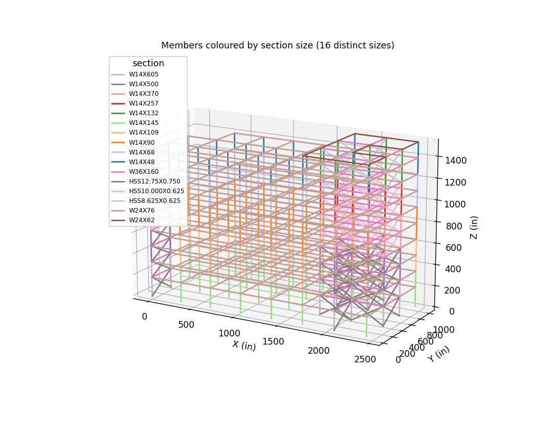
| member | section | demand | gov. combo | limit state | D/C |
|---|---|---|---|---|---|
| roof-W24X62 | W24X62 | P_comp_kip=0.0; P_tens_kip=0.0; Mz_kipin=4682.7; My_kipin=0.0; V_kip=53.82 | 1.2D+1.6Lr+0.5L | flexure (LTB/FLB) + shear | 0.851 |
| floor-W24X76 | W24X76 | P_comp_kip=0.0; P_tens_kip=0.0; Mz_kipin=7316.7; My_kipin=0.0; V_kip=84.1 | 1.2D+1.6L+0.5Lr | flexure (LTB/FLB) + shear | 0.891 |
| floor-W36X160 | W36X160 | P_comp_kip=0.0; P_tens_kip=0.0; Mz_kipin=23782.514800537523; My_kipin=0.0; V_kip=84.1 | 1.2D+1.6L+0.5Lr | flexure (LTB/FLB) + shear | 0.864 |
| roof-W36X160 | W36X160 | P_comp_kip=0.0; P_tens_kip=0.0; Mz_kipin=21148.514800537523; My_kipin=0.0; V_kip=53.82 | 1.2D+1.6Lr+0.5L | flexure (LTB/FLB) + shear | 0.768 |
| brace-HSS10.000X0.625 | HSS10.000X0.625 | P_comp_kip=309.48; P_tens_kip=296.08; Mz_kipin=0.0; My_kipin=0.0; V_kip=0.0 | (1.2+0.2SDS)D+rhoEY+t-+L+0.2S | brace compression E3; A341 highly ductile (round HSS) | 0.597 |
| brace-HSS12.75X0.750 | HSS12.75X0.750 | P_comp_kip=423.64; P_tens_kip=397.49; Mz_kipin=0.0; My_kipin=0.0; V_kip=0.0 | (1.2+0.2SDS)D+rhoEY+t-+L+0.2S | brace compression E3; A341 highly ductile (round HSS) | 0.471 |
| brace-HSS8.625X0.625 | HSS8.625X0.625 | P_comp_kip=130.47; P_tens_kip=108.6; Mz_kipin=0.0; My_kipin=0.0; V_kip=0.0 | (1.2+0.2SDS)D+rhoEX+t++L+0.2S | brace compression E3; A341 highly ductile (round HSS) | 0.332 |
| gravity_col-W14X109 | W14X109 | P_comp_kip=1177.4; P_tens_kip=0.0; Mz_kipin=267.6; My_kipin=89.7; V_kip=1.89 | 1.2D+1.6L+0.5Lr | compression E3 + interaction H1-1a | 0.967 |
| lateral_col-W14X132 | W14X132 | P_comp_kip=286.74; P_tens_kip=32.91; Mz_kipin=200.8; My_kipin=128.3; V_kip=1.66 | (1.2+0.2SDS)D+Om0*EX-+L+0.2S [col] | compression E3 + interaction H1-1b | 0.137 |
| gravity_col-W14X145 | W14X145 | P_comp_kip=1513.8; P_tens_kip=0.0; Mz_kipin=211.8; My_kipin=76.3; V_kip=1.97 | 1.2D+1.6L+0.5Lr | compression E3 + interaction H1-1a | 0.942 |
| lateral_col-W14X257 | W14X257 | P_comp_kip=871.56; P_tens_kip=340.48; Mz_kipin=262.5; My_kipin=92.8; V_kip=3.0 | (1.2+0.2SDS)D+Om0*EX-+L+0.2S [col] | compression E3 + interaction H1-1a | 0.3 |
| lateral_col-W14X370 | W14X370 | P_comp_kip=1636.51; P_tens_kip=878.45; Mz_kipin=1582.7; My_kipin=497.2; V_kip=12.45 | (1.2+0.2SDS)D+Om0*EX-+L+0.2S [col] | compression E3 + interaction H1-1a | 0.434 |
| gravity_col-W14X48 | W14X48 | P_comp_kip=168.2; P_tens_kip=0.0; Mz_kipin=113.1; My_kipin=12.0; V_kip=0.79 | 1.2D+1.6L+0.5Lr | compression E3 + interaction H1-1a | 0.462 |
| lateral_col-W14X500 | W14X500 | P_comp_kip=2521.35; P_tens_kip=1577.23; Mz_kipin=1582.7; My_kipin=497.1; V_kip=11.62 | (1.2+0.2SDS)D+Om0*EX-+L+0.2S [col] | compression E3 + interaction H1-1a | 0.463 |
| lateral_col-W14X605 | W14X605 | P_comp_kip=3479.46; P_tens_kip=2386.99; Mz_kipin=1298.6; My_kipin=359.4; V_kip=12.15 | (1.2+0.2SDS)D+Om0*EX-+L+0.2S [col] | compression E3 + interaction H1-1a | 0.517 |
| gravity_col-W14X68 | W14X68 | P_comp_kip=504.6; P_tens_kip=0.0; Mz_kipin=52.6; My_kipin=8.4; V_kip=0.7 | 1.2D+1.6L+0.5Lr | compression E3 + interaction H1-1a | 0.75 |
| gravity_col-W14X90 | W14X90 | P_comp_kip=841.0; P_tens_kip=0.0; Mz_kipin=267.6; My_kipin=89.7; V_kip=2.09 | 1.2D+1.6L+0.5Lr | compression E3 + interaction H1-1a | 0.853 |
| connection | type | demand | governing limit state | D/C |
|---|---|---|---|---|
| conn-gravity-beam-col | beam-to-column single-plate shear connection | V_kip=95.0 | bolt shear J3.7 (+3 more) | 0.97 |
| conn-SCBF-gusset | brace-to-gusset (slotted HSS, welded), UFM at beam-column | P_kip=1579.0; basis=expected brace strength RyFyAg (AISC 341-22 F2.6c); 2t fold line; UFM | brace-to-gusset fillet welds J2.4 (+2 more) | 0.87 |
| conn-col-splice | column splice (CJP, 4 ft above floor) | P_tens_kip=1600.0; V_kip=0.0 | CJP develops member | 0.24 |
| conn-col-base | column base plate (pinned) | P_kip=4900.0; V_kip=500.0 | shear lug bearing (J8 basis) (+2 more) | 0.89 |
| collector-west-drag | collector (drag strut) + connection at re-entrant/transfer line | P_kip_Omega0=299.0; M_kipin=6500.0; basis=145-ft WEST gravity zone dragged to the east core: continuous grid B/C collectors, Om0=2.0 x diaphragm shear x 1.25 (Type 2 notch + torsional irregularity; 12.10.2.1/12.3.3.4) | H1 interaction | 0.79 |
Member demands already include second-order effects (a P-Δ geometric transformation is applied under every combination), so the AISC 360-22 App.8 B2 amplifier is captured directly by the analysis. The ASCE 7-22 §12.8.7 story stability coefficient θ = PxΔIe/(VxhsxCd) is evaluated per story below; the limit is θmax = min(0.5/(βCd), 0.25) = 0.100 (β = 1.0 conservatively). θ ≤ 0.10 means P-Δ could be neglected; θ > θmax is not permitted.
| Story | Px (kip) | Vx (kip) | hsx (in) | δe % | θ | ≤ 0.100 |
|---|---|---|---|---|---|---|
| 1 | 24728 | 1209 | 180 | 0.082 | 0.017 | OK |
| 2 | 22051 | 1191 | 150 | 0.098 | 0.018 | OK |
| 3 | 19411 | 1153 | 150 | 0.106 | 0.018 | OK |
| 4 | 16770 | 1091 | 150 | 0.113 | 0.017 | OK |
| 5 | 14130 | 1003 | 150 | 0.145 | 0.020 | OK |
| 6 | 11489 | 888 | 150 | 0.144 | 0.019 | OK |
| 7 | 8848 | 743 | 150 | 0.133 | 0.016 | OK |
| 8 | 6208 | 568 | 150 | 0.120 | 0.013 | OK |
| 9 | 3567 | 361 | 150 | 0.107 | 0.011 | OK |
| 10 | 927 | 122 | 144 | 0.094 | 0.007 | OK |
Worst-story θ = 0.020 — within the 0.100 limit; P-Δ effects are small and the analysis includes them regardless.
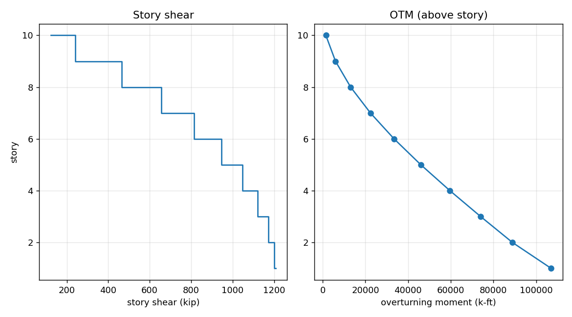
Base shear ΣF = 1209 kip; base overturning ≈ 107078 k-ft.
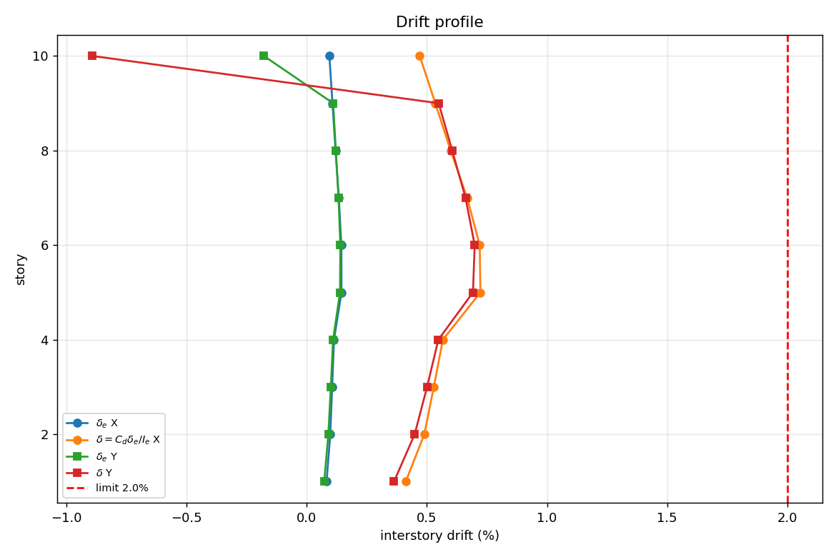
Elastic story drift δe amplified to δ = Cdδe/Ie (§12.8.6, Cd=5.0, Ie=1.0); allowable 2.0% of story height.
| Story | δe X % | δ X % | δe Y % | δ Y % | ≤2.0% |
|---|---|---|---|---|---|
| 1 | 0.082 | 0.412 | 0.073 | 0.363 | OK |
| 2 | 0.098 | 0.489 | 0.090 | 0.449 | OK |
| 3 | 0.106 | 0.529 | 0.100 | 0.501 | OK |
| 4 | 0.113 | 0.566 | 0.110 | 0.548 | OK |
| 5 | 0.145 | 0.723 | 0.138 | 0.692 | OK |
| 6 | 0.144 | 0.720 | 0.140 | 0.699 | OK |
| 7 | 0.133 | 0.667 | 0.132 | 0.661 | OK |
| 8 | 0.120 | 0.599 | 0.121 | 0.605 | OK |
| 9 | 0.107 | 0.535 | 0.110 | 0.549 | OK |
| 10 | 0.094 | 0.470 | -0.179 | -0.893 | OK |
Interstory drift under the design MWFRS wind vs a serviceability limit of h/400 (0.25%). Wind drift has no code-mandated limit (ASCE 7-22 Appendix CC is advisory); a 10-year-MRI service wind may be used for a less conservative check.
| Story | drift X % | drift Y % | ≤ 0.25% |
|---|---|---|---|
| 1 | 0.017 | 0.033 | OK |
| 2 | 0.018 | 0.038 | OK |
| 3 | 0.019 | 0.039 | OK |
| 4 | 0.019 | 0.041 | OK |
| 5 | 0.023 | 0.049 | OK |
| 6 | 0.022 | 0.047 | OK |
| 7 | 0.020 | 0.043 | OK |
| 8 | 0.017 | 0.038 | OK |
| 9 | 0.015 | 0.034 | OK |
| 10 | 0.014 | -0.097 | OK |
Floor/roof beam deflection & camber: no serviceability data in calc_package.json.
Service deflection of the governing floor and roof beam from the static model (chord-relative, true two-way tributary gravity): live load against L/360 and total D+L against L/240. Suggested camber ≈ 80% of the dead-load deflection (nearest 1/4 in) where it exceeds 3/4 in.
| Member | Span | Live δ (vs L/360) | ≤ | Total δ (vs L/240) | ≤ | Camber |
|---|---|---|---|---|---|---|
| Floor beam (governing) | 29 ft | 0.31 in (L/1130) | OK | 0.69 in (L/507) | OK | none |
| Roof beam (governing) | 29 ft | < 0.01 in | OK | 0.10 in (L/3414) | OK | none |
Out of scope (this model): floor vibration (AISC Design Guide 11) and building separation/pounding are detail-level serviceability checks confirmed against the framing drawings.
For the concentrically braced frame (SCBF/OCBF) (R = 6.0), the required AISC 341-22 ductile-detailing and capacity-design checks are listed below. These are derived by the agent from the AISC 341 RAG; values populate from the calc package where present.
| Required check | Basis | Status |
|---|---|---|
| Brace width-thickness | highly/moderately ductile (Table D1.1) | see Appendix A |
| Brace slenderness KL/r | ≤ 200 (SCBF, F2.5b) | see Appendix A |
| Brace connection strength | expected RyFyAg / 1.1RyPn (F2.6c) | see Appendix A |
| Columns & collectors | amplified seismic Ω0 or capacity-limited | see Appendix A |
| Protected zones / gussets | brace ends, gusset hinge zone | see Appendix A |
| Demand-critical welds | AISC 341 A3.4 | see Appendix A |
| Item | Value | ||||||||||||
|---|---|---|---|---|---|---|---|---|---|---|---|---|---|
| system | SCBF (AISC 341-22 F2), R=6, Cd=5, Om0=2, rho=1.3 | ||||||||||||
| torsion classification |
| ||||||||||||
| expected strengths |
| ||||||||||||
| ductility | round HSS diameter-thickness max 18.3, highly-ductile limit 18.4 - OK; slenderness max 81, limit 200 - OK; NO core member exempted | ||||||||||||
| wind torsion | ASCE 7-22 Fig. 27.3-8 torsional load cases noted; seismic torsion governs (Ax-amplified) | ||||||||||||
| vertical irregularity |
|
Width-thickness ductility, AISC 358 prequalification limits, weld NDT and the C&C cladding / net-uplift checks are confirmed on the drawings and connection submittal (delegated).
Connection design demands transmitted to the fabricator / connection engineer (member end forces from the analysis; each connection is then DESIGNED to these demands below):
| Member / location | Connection type | Governing demand | Design basis (limit states) |
|---|---|---|---|
| W24X62 beam | beam-to-column (moment) | V = 54 kip, M = 390 k-ft | CJP flange welds + web bolts (J2/J3) |
| W24X76 beam | beam-to-column (moment) | V = 84 kip, M = 610 k-ft | CJP flange welds + web bolts (J2/J3) |
| W36X160 beam | beam-to-column (moment) | V = 84 kip, M = 1982 k-ft | CJP flange welds + web bolts (J2/J3) |
| W36X160 beam | beam-to-column (moment) | V = 54 kip, M = 1762 k-ft | CJP flange welds + web bolts (J2/J3) |
| HSS10.000X0.625 brace | brace-to-gusset | axial = 309 kip | expected strength (AISC 341 F2.6c) |
| HSS12.75X0.750 brace | brace-to-gusset | axial = 424 kip | expected strength (AISC 341 F2.6c) |
| HSS8.625X0.625 brace | brace-to-gusset | axial = 130 kip | expected strength (AISC 341 F2.6c) |
| W14X109 col | column splice / base | P = 1177 kip, M = 22 k-ft | splice (J1.4) / base plate J8 + ACI 318 Ch.17 |
| W14X132 col | column splice / base | P = 287 kip, M = 17 k-ft | splice (J1.4) / base plate J8 + ACI 318 Ch.17 |
| W14X145 col | column splice / base | P = 1514 kip, M = 18 k-ft | splice (J1.4) / base plate J8 + ACI 318 Ch.17 |
| W14X257 col | column splice / base | P = 872 kip, M = 22 k-ft | splice (J1.4) / base plate J8 + ACI 318 Ch.17 |
| W14X370 col | column splice / base | P = 1637 kip, M = 132 k-ft | splice (J1.4) / base plate J8 + ACI 318 Ch.17 |
| W14X48 col | column splice / base | P = 168 kip, M = 9 k-ft | splice (J1.4) / base plate J8 + ACI 318 Ch.17 |
| W14X500 col | column splice / base | P = 2521 kip, M = 132 k-ft | splice (J1.4) / base plate J8 + ACI 318 Ch.17 |
| W14X605 col | column splice / base | P = 3479 kip, M = 108 k-ft | splice (J1.4) / base plate J8 + ACI 318 Ch.17 |
| W14X68 col | column splice / base | P = 505 kip, M = 4 k-ft | splice (J1.4) / base plate J8 + ACI 318 Ch.17 |
| W14X90 col | column splice / base | P = 841 kip, M = 22 k-ft | splice (J1.4) / base plate J8 + ACI 318 Ch.17 |
| column base | base plate / anchor rods | P = 2093 kip, V = 386 kip | J8/J9 + ACI 318 Ch.17 (min 4 rods) |
Designed in this package: each connection is sized to the demands above per AISC 360 Ch. J (bolts J3, welds J2, block shear J4, HSS Ch. K, base plates/anchors J8/J9 + ACI 318 Ch.17) and AISC 341 for seismic systems — limit state, capacity and D/C ≤ 1.0 derived by the agent from the RAG (see the Connections table in Chapter 6 / Appendix A). Only shop-level detailing is confirmed on the fabricator's connection submittal.
Column base reactions delivered to the foundation design (seismic X combination):
| Quantity | Value |
|---|---|
| Σ vertical to ground ΣRz | 24725 kip |
| Σ horizontal base shear ΣRx | -1209 kip |
| Max single-column vertical reaction | 2093 kip (compression) |
| Min single-column vertical reaction | -515 kip — net uplift |
Net column uplift is governed by the 0.9D−E combinations; the value above is from the seismic-X case shown. Out of scope: foundation/geotechnical design (bearing, sliding, uplift anchorage, footing sizing) is delegated; per-column base reactions are available from the model on request. Overall overturning/sliding stability is confirmed against the geotechnical capacities.
Drawing/specification consistency, general notes, special-inspection schedule, member schedules, framing plans, brace/MF elevations, connection details and the deferred-submittal list are produced and checked on the contract documents, not in this analysis report.
| Check | Result | Status |
|---|---|---|
| Equilibrium — |ΣRx| = applied base shear | 1209 vs 1209 kip | PASS |
| Modal mass ≥ 90% (X / Y) | 99% / 99% | PASS |
| Seismic design drift ≤ limit | 0.72% ≤ 2.0% | PASS |
| Stability θ ≤ θmax | 0.020 ≤ 0.100 | PASS |
Whether the design queried the RAG collections its systems require. R = 6.0 (> 3 — AISC 341 ductile detailing applies).
| Grounding requirement | Applies | Evidence | Status |
|---|---|---|---|
| AISC 360-22 — member limit states | required | 2 queries + cited in calc_package | grounded |
| AISC 360 Ch. J — connection design grounded | required | connections block present | grounded |
| AISC 341-22 — seismic detailing / capacity design | required | 2 queries + capacity_design block + cited in calc_package | grounded |
| AISC 358 — prequalified moment connections | n/a | 0 queries | — |
All required RAG grounding is present.
✓ PASS — every member/connection carries a limit state, capacity and D/C; each headline D/C equals its worst limit-state check and demand÷capacity; and no quantity is reported with conflicting values.
Automated QA evidence in this report: per-combination equilibrium balances to ~0 in all three axes (Chapter 5); every member demand is enveloped over the full ASCE 7-22 combination set (Chapter 4 / Appendix B); each capacity is traceable to a cited AISC clause (Appendix A); and the tool-call activity log is in Appendix C.
Out of scope (engineer judgement): independent third-party check, software validation sign-off, reconciliation of model assumptions against final detailing, and the EOR seal are professional-responsibility steps completed outside the automated package.
For every governing member the framework lists the section properties and the enveloped demand from the analysis combinations. The AISC 360-22 capacity, governing limit state, cited clause, and D/C are derived by the agent from the RAG and shown where recorded in calc_package.json - the framework computes no capacity.
Section properties / geometry (AISC Shapes Database v16):
| A (in2) | Zx (in3) | Sx (in3) | Zy (in3) | Sy (in3) | rx (in) | ry (in) | Aw (in2) | J (in4) | L (in) | Lb (in) |
|---|---|---|---|---|---|---|---|---|---|---|
| 18.2 | 153.0 | 131.0 | 15.7 | 9.8 | 9.23 | 1.38 | 10.19 | 1.71 | 348.0 | 76.0 |
Demand envelope (analysis):
| P_comp (kip) | P_tens (kip) | Mz (kip-in) | My (kip-in) | V (kip) | governing combo |
|---|---|---|---|---|---|
| 0.0 | 0.0 | 4682.7 | 0.0 | 53.82 | 1.2D+1.6Lr+0.5L |
| Quantity | Calculation | Value | Ref. (AISC) |
|---|---|---|---|
| Governing limit state | selected from AISC 360 | flexure (LTB/FLB) + shear | AISC 360-22 F2 (F2-2 (inelastic LTB)), phi_b=0.90 (F1); flange compact (Table B4.1b); AISC 360-22 G2.1(a): Vn=0.6FyAwCv1 (G2-1), Cv1=1.0, phi_v=1.00 |
| phiMn_kipin | 5502.0 | ||
| phiVn_kip | 305.7 | ||
| Lb_in | 116.0 | ||
| Cb | 1.0 | ||
| D/C | demand / capacity | 0.851 ok | AISC 360-22 F2 (F2-2 (inelastic LTB)), phi_b=0.90 (F1); flange compact (Table B4.1b); AISC 360-22 G2.1(a): Vn=0.6FyAwCv1 (G2-1), Cv1=1.0, phi_v=1.00 |
Section properties / geometry (AISC Shapes Database v16):
| A (in2) | Zx (in3) | Sx (in3) | Zy (in3) | Sy (in3) | rx (in) | ry (in) | Aw (in2) | J (in4) | L (in) | Lb (in) |
|---|---|---|---|---|---|---|---|---|---|---|
| 22.4 | 200.0 | 176.0 | 28.6 | 18.4 | 9.69 | 1.92 | 10.52 | 2.68 | 348.0 | 105.8 |
Demand envelope (analysis):
| P_comp (kip) | P_tens (kip) | Mz (kip-in) | My (kip-in) | V (kip) | governing combo |
|---|---|---|---|---|---|
| 0.0 | 0.0 | 7316.7 | 0.0 | 84.1 | 1.2D+1.6L+0.5Lr |
| Quantity | Calculation | Value | Ref. (AISC) |
|---|---|---|---|
| Governing limit state | selected from AISC 360 | flexure (LTB/FLB) + shear | AISC 360-22 F2 (F2-2 (inelastic LTB)), phi_b=0.90 (F1); flange compact (Table B4.1b); AISC 360-22 G2.1(a): Vn=0.6FyAwCv1 (G2-1), Cv1=1.0, phi_v=1.00 |
| phiMn_kipin | 8216.0 | ||
| phiVn_kip | 315.5 | ||
| Lb_in | 116.0 | ||
| Cb | 1.0 | ||
| D/C | demand / capacity | 0.891 ok | AISC 360-22 F2 (F2-2 (inelastic LTB)), phi_b=0.90 (F1); flange compact (Table B4.1b); AISC 360-22 G2.1(a): Vn=0.6FyAwCv1 (G2-1), Cv1=1.0, phi_v=1.00 |
Section properties / geometry (AISC Shapes Database v16):
| A (in2) | Zx (in3) | Sx (in3) | Zy (in3) | Sy (in3) | rx (in) | ry (in) | Aw (in2) | J (in4) | L (in) | Lb (in) |
|---|---|---|---|---|---|---|---|---|---|---|
| 47.0 | 624.0 | 542.0 | 77.3 | 49.1 | 14.4 | 2.5 | 23.4 | 12.4 | 348.0 | 137.8 |
Demand envelope (analysis):
| P_comp (kip) | P_tens (kip) | Mz (kip-in) | My (kip-in) | V (kip) | governing combo |
|---|---|---|---|---|---|
| 0.0 | 0.0 | 23782.514800537523 | 0.0 | 84.1 | 1.2D+1.6L+0.5Lr |
| Quantity | Calculation | Value | Ref. (AISC) |
|---|---|---|---|
| Governing limit state | selected from AISC 360 | flexure (LTB/FLB) + shear | AISC 360-22 F2 (F2-2 (inelastic LTB)), phi_b=0.90 (F1); flange compact (Table B4.1b); AISC 360-22 G2.1(a): Vn=0.6FyAwCv1 (G2-1), Cv1=1.0, phi_v=1.00; braced-bay intermediate beam includes two-story-X unbalanced force (T-0.3C)sin(theta) per AISC 341-22 F2.3 analysis (b) |
| phiMn_kipin | 27539.0 | ||
| phiVn_kip | 702.0 | ||
| Lb_in | 116.0 | ||
| Cb | 1.0 | ||
| D/C | demand / capacity | 0.864 ok | AISC 360-22 F2 (F2-2 (inelastic LTB)), phi_b=0.90 (F1); flange compact (Table B4.1b); AISC 360-22 G2.1(a): Vn=0.6FyAwCv1 (G2-1), Cv1=1.0, phi_v=1.00; braced-bay intermediate beam includes two-story-X unbalanced force (T-0.3C)sin(theta) per AISC 341-22 F2.3 analysis (b) |
Section properties / geometry (AISC Shapes Database v16):
| A (in2) | Zx (in3) | Sx (in3) | Zy (in3) | Sy (in3) | rx (in) | ry (in) | Aw (in2) | J (in4) | L (in) | Lb (in) |
|---|---|---|---|---|---|---|---|---|---|---|
| 47.0 | 624.0 | 542.0 | 77.3 | 49.1 | 14.4 | 2.5 | 23.4 | 12.4 | 348.0 | 137.8 |
Demand envelope (analysis):
| P_comp (kip) | P_tens (kip) | Mz (kip-in) | My (kip-in) | V (kip) | governing combo |
|---|---|---|---|---|---|
| 0.0 | 0.0 | 21148.514800537523 | 0.0 | 53.82 | 1.2D+1.6Lr+0.5L |
| Quantity | Calculation | Value | Ref. (AISC) |
|---|---|---|---|
| Governing limit state | selected from AISC 360 | flexure (LTB/FLB) + shear | AISC 360-22 F2 (F2-2 (inelastic LTB)), phi_b=0.90 (F1); flange compact (Table B4.1b); AISC 360-22 G2.1(a): Vn=0.6FyAwCv1 (G2-1), Cv1=1.0, phi_v=1.00; braced-bay intermediate beam includes two-story-X unbalanced force (T-0.3C)sin(theta) per AISC 341-22 F2.3 analysis (b) |
| phiMn_kipin | 27539.0 | ||
| phiVn_kip | 702.0 | ||
| Lb_in | 116.0 | ||
| Cb | 1.0 | ||
| D/C | demand / capacity | 0.768 ok | AISC 360-22 F2 (F2-2 (inelastic LTB)), phi_b=0.90 (F1); flange compact (Table B4.1b); AISC 360-22 G2.1(a): Vn=0.6FyAwCv1 (G2-1), Cv1=1.0, phi_v=1.00; braced-bay intermediate beam includes two-story-X unbalanced force (T-0.3C)sin(theta) per AISC 341-22 F2.3 analysis (b) |
Section properties / geometry (AISC Shapes Database v16):
| r (in) | L (in) |
|---|---|
| 3.34 | 379.0 |
Demand envelope (analysis):
| P_comp (kip) | P_tens (kip) | Mz (kip-in) | My (kip-in) | V (kip) | governing combo |
|---|---|---|---|---|---|
| 309.48 | 296.08 | 0.0 | 0.0 | 0.0 | (1.2+0.2SDS)D+rhoEY+t-+L+0.2S |
| Quantity | Calculation | Value | Ref. (AISC) |
|---|---|---|---|
| Governing limit state | selected from AISC 360 | brace compression E3; A341 highly ductile (round HSS) | AISC 360-22 E3 (Eqs. E3-1, E3-2, E3-4), phi_c=0.90 (E1); AISC 341-22 Table D1.1a Case 16: D/t=17.2 <= 18.4 OK; KL/r=69 <= 200 (F2.5b); expected strengths (F2.3): T=1029, C=775, post-buckling=233 kip |
| phiPn_kip | 518.0 | ||
| expected_T_kip | 1029.0 | ||
| D/C | demand / capacity | 0.597 ok | AISC 360-22 E3 (Eqs. E3-1, E3-2, E3-4), phi_c=0.90 (E1); AISC 341-22 Table D1.1a Case 16: D/t=17.2 <= 18.4 OK; KL/r=69 <= 200 (F2.5b); expected strengths (F2.3): T=1029, C=775, post-buckling=233 kip |
Section properties / geometry (AISC Shapes Database v16):
| r (in) | L (in) |
|---|---|
| 2.5 | 391.8 |
Demand envelope (analysis):
| P_comp (kip) | P_tens (kip) | Mz (kip-in) | My (kip-in) | V (kip) | governing combo |
|---|---|---|---|---|---|
| 423.64 | 397.49 | 0.0 | 0.0 | 0.0 | (1.2+0.2SDS)D+rhoEY+t-+L+0.2S |
| Quantity | Calculation | Value | Ref. (AISC) |
|---|---|---|---|
| Governing limit state | selected from AISC 360 | brace compression E3; A341 highly ductile (round HSS) | AISC 360-22 E3 (Eqs. E3-1, E3-2, E3-4), phi_c=0.90 (E1); AISC 341-22 Table D1.1a Case 16: D/t=18.3 <= 18.4 OK; KL/r=54 <= 200 (F2.5b); expected strengths (F2.3): T=1579, C=1398, post-buckling=419 kip |
| phiPn_kip | 900.0 | ||
| expected_T_kip | 1579.0 | ||
| D/C | demand / capacity | 0.471 ok | AISC 360-22 E3 (Eqs. E3-1, E3-2, E3-4), phi_c=0.90 (E1); AISC 341-22 Table D1.1a Case 16: D/t=18.3 <= 18.4 OK; KL/r=54 <= 200 (F2.5b); expected strengths (F2.3): T=1579, C=1398, post-buckling=419 kip |
Section properties / geometry (AISC Shapes Database v16):
| r (in) | L (in) |
|---|---|
| 2.85 | 379.0 |
Demand envelope (analysis):
| P_comp (kip) | P_tens (kip) | Mz (kip-in) | My (kip-in) | V (kip) | governing combo |
|---|---|---|---|---|---|
| 130.47 | 108.6 | 0.0 | 0.0 | 0.0 | (1.2+0.2SDS)D+rhoEX+t++L+0.2S |
| Quantity | Calculation | Value | Ref. (AISC) |
|---|---|---|---|
| Governing limit state | selected from AISC 360 | brace compression E3; A341 highly ductile (round HSS) | AISC 360-22 E3 (Eqs. E3-1, E3-2, E3-4), phi_c=0.90 (E1); AISC 341-22 Table D1.1a Case 16: D/t=14.8 <= 18.4 OK; KL/r=81 <= 200 (F2.5b); expected strengths (F2.3): T=879, C=568, post-buckling=170 kip |
| phiPn_kip | 393.0 | ||
| expected_T_kip | 879.0 | ||
| D/C | demand / capacity | 0.332 ok | AISC 360-22 E3 (Eqs. E3-1, E3-2, E3-4), phi_c=0.90 (E1); AISC 341-22 Table D1.1a Case 16: D/t=14.8 <= 18.4 OK; KL/r=81 <= 200 (F2.5b); expected strengths (F2.3): T=879, C=568, post-buckling=170 kip |
Section properties / geometry (AISC Shapes Database v16):
| A (in2) | Zx (in3) | Sx (in3) | Zy (in3) | Sy (in3) | rx (in) | ry (in) | Aw (in2) | J (in4) | L (in) | Lb (in) |
|---|---|---|---|---|---|---|---|---|---|---|
| 32.0 | 192.0 | 173.0 | 92.7 | 61.2 | 6.22 | 3.73 | 7.51 | 7.12 | 150.0 | 150.0 |
Demand envelope (analysis):
| P_comp (kip) | P_tens (kip) | Mz (kip-in) | My (kip-in) | V (kip) | governing combo |
|---|---|---|---|---|---|
| 1177.4 | 0.0 | 267.6 | 89.7 | 1.89 | 1.2D+1.6L+0.5Lr |
| Quantity | Calculation | Value | Ref. (AISC) |
|---|---|---|---|
| Governing limit state | selected from AISC 360 | compression E3 + interaction H1-1a | AISC 360-22 E3 (Eqs. E3-1, E3-2, E3-4), phi_c=0.90 (E1); AISC 360-22 F2 (F2-1 (Lb<=Lp: LTB does not apply)), phi_b=0.90 (F1); flange compact (Table B4.1b); AISC 360-22 H1.1 Eq. H1-1a |
| phiPn_kip | 1279.0 | ||
| phiMnx_kipin | 8640.0 | ||
| phiMny_kipin | 4172.0 | ||
| Lc_in | 150.0 | ||
| D/C | demand / capacity | 0.967 ok | AISC 360-22 E3 (Eqs. E3-1, E3-2, E3-4), phi_c=0.90 (E1); AISC 360-22 F2 (F2-1 (Lb<=Lp: LTB does not apply)), phi_b=0.90 (F1); flange compact (Table B4.1b); AISC 360-22 H1.1 Eq. H1-1a |
Section properties / geometry (AISC Shapes Database v16):
| A (in2) | Zx (in3) | Sx (in3) | Zy (in3) | Sy (in3) | rx (in) | ry (in) | Aw (in2) | J (in4) | L (in) | Lb (in) |
|---|---|---|---|---|---|---|---|---|---|---|
| 38.8 | 234.0 | 209.0 | 113.0 | 74.5 | 6.28 | 3.76 | 9.48 | 12.3 | 150.0 | 150.0 |
Demand envelope (analysis):
| P_comp (kip) | P_tens (kip) | Mz (kip-in) | My (kip-in) | V (kip) | governing combo |
|---|---|---|---|---|---|
| 286.74 | 32.91 | 200.8 | 128.3 | 1.66 | (1.2+0.2SDS)D+Om0*EX-+L+0.2S [col] |
| Quantity | Calculation | Value | Ref. (AISC) |
|---|---|---|---|
| Governing limit state | selected from AISC 360 | compression E3 + interaction H1-1b | AISC 360-22 E3 (Eqs. E3-1, E3-2, E3-4), phi_c=0.90 (E1); AISC 360-22 F2 (F2-1 (Lb<=Lp: LTB does not apply)), phi_b=0.90 (F1); flange compact (Table B4.1b); AISC 360-22 H1.1 Eq. H1-1b; required strength: larger of Om0 envelope and F2.3 mechanism (tension+0.3C), the latter capped per F2.3 Exc.(b)(1) foundation uplift (stated) |
| phiPn_kip | 1554.0 | ||
| phiMnx_kipin | 10530.0 | ||
| phiMny_kipin | 5085.0 | ||
| Lc_in | 150.0 | ||
| D/C | demand / capacity | 0.137 ok | AISC 360-22 E3 (Eqs. E3-1, E3-2, E3-4), phi_c=0.90 (E1); AISC 360-22 F2 (F2-1 (Lb<=Lp: LTB does not apply)), phi_b=0.90 (F1); flange compact (Table B4.1b); AISC 360-22 H1.1 Eq. H1-1b; required strength: larger of Om0 envelope and F2.3 mechanism (tension+0.3C), the latter capped per F2.3 Exc.(b)(1) foundation uplift (stated) |
Section properties / geometry (AISC Shapes Database v16):
| A (in2) | Zx (in3) | Sx (in3) | Zy (in3) | Sy (in3) | rx (in) | ry (in) | Aw (in2) | J (in4) | L (in) | Lb (in) |
|---|---|---|---|---|---|---|---|---|---|---|
| 42.7 | 260.0 | 232.0 | 133.0 | 87.3 | 6.33 | 3.98 | 10.06 | 15.2 | 180.0 | 180.0 |
Demand envelope (analysis):
| P_comp (kip) | P_tens (kip) | Mz (kip-in) | My (kip-in) | V (kip) | governing combo |
|---|---|---|---|---|---|
| 1513.8 | 0.0 | 211.8 | 76.3 | 1.97 | 1.2D+1.6L+0.5Lr |
| Quantity | Calculation | Value | Ref. (AISC) |
|---|---|---|---|
| Governing limit state | selected from AISC 360 | compression E3 + interaction H1-1a | AISC 360-22 E3 (Eqs. E3-1, E3-2, E3-4), phi_c=0.90 (E1); AISC 360-22 F2 (F2-2 (inelastic LTB)), phi_b=0.90 (F1); flange compact (Table B4.1b); AISC 360-22 H1.1 Eq. H1-1a |
| phiPn_kip | 1655.0 | ||
| phiMnx_kipin | 11613.0 | ||
| phiMny_kipin | 5985.0 | ||
| Lc_in | 180.0 | ||
| D/C | demand / capacity | 0.942 ok | AISC 360-22 E3 (Eqs. E3-1, E3-2, E3-4), phi_c=0.90 (E1); AISC 360-22 F2 (F2-2 (inelastic LTB)), phi_b=0.90 (F1); flange compact (Table B4.1b); AISC 360-22 H1.1 Eq. H1-1a |
Section properties / geometry (AISC Shapes Database v16):
| A (in2) | Zx (in3) | Sx (in3) | Zy (in3) | Sy (in3) | rx (in) | ry (in) | Aw (in2) | J (in4) | L (in) | Lb (in) |
|---|---|---|---|---|---|---|---|---|---|---|
| 75.6 | 487.0 | 415.0 | 246.0 | 161.0 | 6.71 | 4.13 | 19.35 | 79.1 | 150.0 | 150.0 |
Demand envelope (analysis):
| P_comp (kip) | P_tens (kip) | Mz (kip-in) | My (kip-in) | V (kip) | governing combo |
|---|---|---|---|---|---|
| 871.56 | 340.48 | 262.5 | 92.8 | 3.0 | (1.2+0.2SDS)D+Om0*EX-+L+0.2S [col] |
| Quantity | Calculation | Value | Ref. (AISC) |
|---|---|---|---|
| Governing limit state | selected from AISC 360 | compression E3 + interaction H1-1a | AISC 360-22 E3 (Eqs. E3-1, E3-2, E3-4), phi_c=0.90 (E1); AISC 360-22 F2 (F2-1 (Lb<=Lp: LTB does not apply)), phi_b=0.90 (F1); flange compact (Table B4.1b); AISC 360-22 H1.1 Eq. H1-1a; required strength: larger of Om0 envelope and F2.3 mechanism (tension+0.3C), the latter capped per F2.3 Exc.(b)(1) foundation uplift (stated) |
| phiPn_kip | 3089.0 | ||
| phiMnx_kipin | 21915.0 | ||
| phiMny_kipin | 11070.0 | ||
| Lc_in | 150.0 | ||
| D/C | demand / capacity | 0.3 ok | AISC 360-22 E3 (Eqs. E3-1, E3-2, E3-4), phi_c=0.90 (E1); AISC 360-22 F2 (F2-1 (Lb<=Lp: LTB does not apply)), phi_b=0.90 (F1); flange compact (Table B4.1b); AISC 360-22 H1.1 Eq. H1-1a; required strength: larger of Om0 envelope and F2.3 mechanism (tension+0.3C), the latter capped per F2.3 Exc.(b)(1) foundation uplift (stated) |
Section properties / geometry (AISC Shapes Database v16):
| A (in2) | Zx (in3) | Sx (in3) | Zy (in3) | Sy (in3) | rx (in) | ry (in) | Aw (in2) | J (in4) | L (in) | Lb (in) |
|---|---|---|---|---|---|---|---|---|---|---|
| 109.0 | 736.0 | 607.0 | 370.0 | 241.0 | 7.07 | 4.27 | 29.71 | 222.0 | 150.0 | 150.0 |
Demand envelope (analysis):
| P_comp (kip) | P_tens (kip) | Mz (kip-in) | My (kip-in) | V (kip) | governing combo |
|---|---|---|---|---|---|
| 1636.51 | 878.45 | 1582.7 | 497.2 | 12.45 | (1.2+0.2SDS)D+Om0*EX-+L+0.2S [col] |
| Quantity | Calculation | Value | Ref. (AISC) |
|---|---|---|---|
| Governing limit state | selected from AISC 360 | compression E3 + interaction H1-1a | AISC 360-22 E3 (Eqs. E3-1, E3-2, E3-4), phi_c=0.90 (E1); AISC 360-22 F2 (F2-1 (Lb<=Lp: LTB does not apply)), phi_b=0.90 (F1); flange compact (Table B4.1b); AISC 360-22 H1.1 Eq. H1-1a; required strength: larger of Om0 envelope and F2.3 mechanism (tension+0.3C), the latter capped per F2.3 Exc.(b)(1) foundation uplift (stated) |
| phiPn_kip | 4482.0 | ||
| phiMnx_kipin | 33120.0 | ||
| phiMny_kipin | 16650.0 | ||
| Lc_in | 150.0 | ||
| D/C | demand / capacity | 0.434 ok | AISC 360-22 E3 (Eqs. E3-1, E3-2, E3-4), phi_c=0.90 (E1); AISC 360-22 F2 (F2-1 (Lb<=Lp: LTB does not apply)), phi_b=0.90 (F1); flange compact (Table B4.1b); AISC 360-22 H1.1 Eq. H1-1a; required strength: larger of Om0 envelope and F2.3 mechanism (tension+0.3C), the latter capped per F2.3 Exc.(b)(1) foundation uplift (stated) |
Section properties / geometry (AISC Shapes Database v16):
| A (in2) | Zx (in3) | Sx (in3) | Zy (in3) | Sy (in3) | rx (in) | ry (in) | Aw (in2) | J (in4) | L (in) | Lb (in) |
|---|---|---|---|---|---|---|---|---|---|---|
| 14.1 | 78.4 | 70.2 | 19.6 | 12.8 | 5.85 | 1.91 | 4.69 | 1.45 | 150.0 | 150.0 |
Demand envelope (analysis):
| P_comp (kip) | P_tens (kip) | Mz (kip-in) | My (kip-in) | V (kip) | governing combo |
|---|---|---|---|---|---|
| 168.2 | 0.0 | 113.1 | 12.0 | 0.79 | 1.2D+1.6L+0.5Lr |
| Quantity | Calculation | Value | Ref. (AISC) |
|---|---|---|---|
| Governing limit state | selected from AISC 360 | compression E3 + interaction H1-1a | AISC 360-22 E3 (Eqs. E3-1, E3-2, E3-4), phi_c=0.90 (E1); AISC 360-22 F2 (F2-2 (inelastic LTB)), phi_b=0.90 (F1); flange compact (Table B4.1b); AISC 360-22 H1.1 Eq. H1-1a |
| phiPn_kip | 404.0 | ||
| phiMnx_kipin | 3000.0 | ||
| phiMny_kipin | 882.0 | ||
| Lc_in | 150.0 | ||
| D/C | demand / capacity | 0.462 ok | AISC 360-22 E3 (Eqs. E3-1, E3-2, E3-4), phi_c=0.90 (E1); AISC 360-22 F2 (F2-2 (inelastic LTB)), phi_b=0.90 (F1); flange compact (Table B4.1b); AISC 360-22 H1.1 Eq. H1-1a |
Section properties / geometry (AISC Shapes Database v16):
| A (in2) | Zx (in3) | Sx (in3) | Zy (in3) | Sy (in3) | rx (in) | ry (in) | Aw (in2) | J (in4) | L (in) | Lb (in) |
|---|---|---|---|---|---|---|---|---|---|---|
| 147.0 | 1050.0 | 838.0 | 522.0 | 339.0 | 7.48 | 4.43 | 42.92 | 514.0 | 150.0 | 150.0 |
Demand envelope (analysis):
| P_comp (kip) | P_tens (kip) | Mz (kip-in) | My (kip-in) | V (kip) | governing combo |
|---|---|---|---|---|---|
| 2521.35 | 1577.23 | 1582.7 | 497.1 | 11.62 | (1.2+0.2SDS)D+Om0*EX-+L+0.2S [col] |
| Quantity | Calculation | Value | Ref. (AISC) |
|---|---|---|---|
| Governing limit state | selected from AISC 360 | compression E3 + interaction H1-1a | AISC 360-22 E3 (Eqs. E3-1, E3-2, E3-4), phi_c=0.90 (E1); AISC 360-22 F2 (F2-1 (Lb<=Lp: LTB does not apply)), phi_b=0.90 (F1); flange compact (Table B4.1b); AISC 360-22 H1.1 Eq. H1-1a; required strength: larger of Om0 envelope and F2.3 mechanism (tension+0.3C), the latter capped per F2.3 Exc.(b)(1) foundation uplift (stated) |
| phiPn_kip | 6083.0 | ||
| phiMnx_kipin | 47250.0 | ||
| phiMny_kipin | 23490.0 | ||
| Lc_in | 150.0 | ||
| D/C | demand / capacity | 0.463 ok | AISC 360-22 E3 (Eqs. E3-1, E3-2, E3-4), phi_c=0.90 (E1); AISC 360-22 F2 (F2-1 (Lb<=Lp: LTB does not apply)), phi_b=0.90 (F1); flange compact (Table B4.1b); AISC 360-22 H1.1 Eq. H1-1a; required strength: larger of Om0 envelope and F2.3 mechanism (tension+0.3C), the latter capped per F2.3 Exc.(b)(1) foundation uplift (stated) |
Section properties / geometry (AISC Shapes Database v16):
| A (in2) | Zx (in3) | Sx (in3) | Zy (in3) | Sy (in3) | rx (in) | ry (in) | Aw (in2) | J (in4) | L (in) | Lb (in) |
|---|---|---|---|---|---|---|---|---|---|---|
| 178.0 | 1320.0 | 1040.0 | 652.0 | 423.0 | 7.8 | 4.55 | 54.34 | 869.0 | 180.0 | 180.0 |
Demand envelope (analysis):
| P_comp (kip) | P_tens (kip) | Mz (kip-in) | My (kip-in) | V (kip) | governing combo |
|---|---|---|---|---|---|
| 3479.46 | 2386.99 | 1298.6 | 359.4 | 12.15 | (1.2+0.2SDS)D+Om0*EX-+L+0.2S [col] |
| Quantity | Calculation | Value | Ref. (AISC) |
|---|---|---|---|
| Governing limit state | selected from AISC 360 | compression E3 + interaction H1-1a | AISC 360-22 E3 (Eqs. E3-1, E3-2, E3-4), phi_c=0.90 (E1); AISC 360-22 F2 (F2-1 (Lb<=Lp: LTB does not apply)), phi_b=0.90 (F1); flange compact (Table B4.1b); AISC 360-22 H1.1 Eq. H1-1a; required strength: larger of Om0 envelope and F2.3 mechanism (tension+0.3C), the latter capped per F2.3 Exc.(b)(1) foundation uplift (stated) |
| phiPn_kip | 7144.0 | ||
| phiMnx_kipin | 59400.0 | ||
| phiMny_kipin | 29340.0 | ||
| Lc_in | 180.0 | ||
| D/C | demand / capacity | 0.517 ok | AISC 360-22 E3 (Eqs. E3-1, E3-2, E3-4), phi_c=0.90 (E1); AISC 360-22 F2 (F2-1 (Lb<=Lp: LTB does not apply)), phi_b=0.90 (F1); flange compact (Table B4.1b); AISC 360-22 H1.1 Eq. H1-1a; required strength: larger of Om0 envelope and F2.3 mechanism (tension+0.3C), the latter capped per F2.3 Exc.(b)(1) foundation uplift (stated) |
Section properties / geometry (AISC Shapes Database v16):
| A (in2) | Zx (in3) | Sx (in3) | Zy (in3) | Sy (in3) | rx (in) | ry (in) | Aw (in2) | J (in4) | L (in) | Lb (in) |
|---|---|---|---|---|---|---|---|---|---|---|
| 20.0 | 115.0 | 103.0 | 36.9 | 24.2 | 6.01 | 2.46 | 5.81 | 3.01 | 150.0 | 150.0 |
Demand envelope (analysis):
| P_comp (kip) | P_tens (kip) | Mz (kip-in) | My (kip-in) | V (kip) | governing combo |
|---|---|---|---|---|---|
| 504.6 | 0.0 | 52.6 | 8.4 | 0.7 | 1.2D+1.6L+0.5Lr |
| Quantity | Calculation | Value | Ref. (AISC) |
|---|---|---|---|
| Governing limit state | selected from AISC 360 | compression E3 + interaction H1-1a | AISC 360-22 E3 (Eqs. E3-1, E3-2, E3-4), phi_c=0.90 (E1); AISC 360-22 F2 (F2-2 (inelastic LTB)), phi_b=0.90 (F1); flange compact (Table B4.1b); AISC 360-22 H1.1 Eq. H1-1a |
| phiPn_kip | 686.0 | ||
| phiMnx_kipin | 4818.0 | ||
| phiMny_kipin | 1660.0 | ||
| Lc_in | 150.0 | ||
| D/C | demand / capacity | 0.75 ok | AISC 360-22 E3 (Eqs. E3-1, E3-2, E3-4), phi_c=0.90 (E1); AISC 360-22 F2 (F2-2 (inelastic LTB)), phi_b=0.90 (F1); flange compact (Table B4.1b); AISC 360-22 H1.1 Eq. H1-1a |
Section properties / geometry (AISC Shapes Database v16):
| A (in2) | Zx (in3) | Sx (in3) | Zy (in3) | Sy (in3) | rx (in) | ry (in) | Aw (in2) | J (in4) | L (in) | Lb (in) |
|---|---|---|---|---|---|---|---|---|---|---|
| 26.5 | 157.0 | 143.0 | 75.6 | 49.9 | 6.14 | 3.7 | 6.16 | 4.06 | 150.0 | 150.0 |
Demand envelope (analysis):
| P_comp (kip) | P_tens (kip) | Mz (kip-in) | My (kip-in) | V (kip) | governing combo |
|---|---|---|---|---|---|
| 841.0 | 0.0 | 267.6 | 89.7 | 2.09 | 1.2D+1.6L+0.5Lr |
| Quantity | Calculation | Value | Ref. (AISC) |
|---|---|---|---|
| Governing limit state | selected from AISC 360 | compression E3 + interaction H1-1a | AISC 360-22 E3 (Eqs. E3-1, E3-2, E3-4), phi_c=0.90 (E1); AISC 360-22 F3 (noncompact flange, Table B4.1b): LTB per F2.2 + FLB Eq. F3-1; governing F3-1 FLB; phi_b=0.90 (F1); AISC 360-22 H1.1 Eq. H1-1a |
| phiPn_kip | 1057.0 | ||
| phiMnx_kipin | 6883.0 | ||
| phiMny_kipin | 3402.0 | ||
| Lc_in | 150.0 | ||
| D/C | demand / capacity | 0.853 ok | AISC 360-22 E3 (Eqs. E3-1, E3-2, E3-4), phi_c=0.90 (E1); AISC 360-22 F3 (noncompact flange, Table B4.1b): LTB per F2.2 + FLB Eq. F3-1; governing F3-1 FLB; phi_b=0.90 (F1); AISC 360-22 H1.1 Eq. H1-1a |
Demand: V_kip=95.0
Components: PL 3/8 x 15 in. A572-50, (4) 7/8-in. A325-N bolts @3 in., 4/16 fillet both sides
Cited: AISC 360-22 J2.4/J3.7/J3.11/J4
| Limit state | D/C | ≤1.0 |
|---|---|---|
| bolt shear J3.7 | 0.97 | OK |
| bolt bearing/tearout J3.11 | 0.62 | OK |
| plate shear yield/rupture J4.2 | 0.79 | OK |
| plate-to-column fillet weld J2.4 | 0.57 | OK |
Demand: P_kip=1579.0; basis=expected brace strength RyFyAg (AISC 341-22 F2.6c); 2t fold line; UFM
Components: PL 0.75 in. A572-50 gusset, (4) 6/16-in. fillets x 54 in., 2t fold line per AISC 341
Cited: AISC 360-22 J2.4/J4.1/J4.3/J4.4 + AISC 341-22 F2.6c/F3.6
| Limit state | D/C | ≤1.0 |
|---|---|---|
| brace-to-gusset fillet welds J2.4 | 0.87 | OK |
| gusset tension yield on Whitmore J4.1 | 0.72 | OK |
| gusset compression buckling (Whitmore, E3 per J4.4) | 0.82 | OK |
Demand: P_tens_kip=1600.0; V_kip=0.0
Components: CJP groove welds both flanges + web per AISC 341-22 D2.5 (demand-critical), located 4 ft above floor
Cited: AISC 341-22 D2.5 + AISC 360-22 J2.6 (CJP develops base metal, Table J2.5)
| Limit state | D/C | ≤1.0 |
|---|---|---|
| CJP develops member (tension) | 0.24 | OK |
Demand: P_kip=4900.0; V_kip=500.0
Components: PL 5 x 33 x 29 in. A36, (4) 1-1/4 in. F1554 Gr36 rods, 5/16 fillets, 6x14.0774x1.25 in. shear lug; grout on conc. fc'=6 ksi
Cited: AISC 360-22 J8/J9 + Manual Pt 14; anchorage to ACI 318 Ch.17 (delegated)
| Limit state | D/C | ≤1.0 |
|---|---|---|
| concrete bearing J8 | 0.76 | OK |
| plate flexure (cantilever m; Manual Pt 14 / J8) | 0.87 | OK |
| shear lug bearing (J8 basis) | 0.89 | OK |
Demand: P_kip_Omega0=299.0; M_kipin=6500.0; basis=145-ft WEST gravity zone dragged to the east core: continuous grid B/C collectors, Om0=2.0 x diaphragm shear x 1.25 (Type 2 notch + torsional irregularity; 12.10.2.1/12.3.3.4)
Components: W27X94 continuous; welded flange-plate connection to column developing Pu
Cited: AISC 360-22 E3 (Eqs. E3-1, E3-2, E3-4), phi_c=0.90 (E1); AISC 360-22 F2 (F2-2 (inelastic LTB)), phi_b=0.90 (F1); flange compact (Table B4.1b); AISC 360-22 H1.1 Eq. H1-1a
| Limit state | D/C | ≤1.0 |
|---|---|---|
| combined axial+flexure H1 (utilization, unitless) | 0.79 | OK |
Full per-combination detail (summarised in Chapter 4): the worst member of each type with its location, from the static model (true distributed gravity). The per-combination N / V / M diagrams are written to the figs/ folder (case_<label>.png) for review — not embedded here, to keep the report compact. The headline governing diagrams (perimeter + internal) are in Chapter 5.
Dead load only — the basic gravity check.
| member | section | N (kip) | Mz (k-ft) | My (k-ft) | V (kip) | location (i,j / level) |
|---|---|---|---|---|---|---|
| beam | W24X62 | 0.0 | 276.6 | 0.0 | 29.4 | (6,1)→(7,1) level 10 |
| beam | W24X76 | 0.0 | 221.3 | 0.0 | 23.5 | (4,1)→(4,2) level 8 |
| beam | W36X160 | 0.0 | 276.6 | 0.0 | 29.4 | (6,0)→(6,1) level 10 |
| brace | HSS10.000X0.625 | -25.3 | 0.0 | 0.0 | 0.0 | — |
| brace | HSS12.75X0.750 | -28.0 | 0.0 | 0.0 | 0.0 | — |
| brace | HSS8.625X0.625 | -25.6 | 0.0 | 0.0 | 0.0 | — |
| col | W14X109 | 659.3 | 0.3 | 0.1 | 0.0 | (1,1) level 2→3 |
| col | W14X132 | 182.0 | 0.0 | 0.5 | 0.1 | (6,2) level 8→9 |
| col | W14X145 | 847.7 | 0.4 | 0.2 | 0.0 | (1,1) level 0→1 |
| col | W14X257 | 348.8 | 0.4 | 0.0 | 0.0 | (5,2) level 6→7 |
| col | W14X370 | 540.7 | 0.8 | 0.1 | 0.0 | (5,2) level 4→5 |
| col | W14X48 | 94.2 | 0.0 | 0.0 | 0.0 | (1,1) level 8→9 |
| col | W14X500 | 729.6 | 1.2 | 0.1 | 0.0 | (5,2) level 2→3 |
| col | W14X605 | 914.9 | 2.4 | 0.2 | 0.2 | (5,1) level 0→1 |
| col | W14X68 | 282.6 | 0.1 | 0.0 | 0.0 | (1,1) level 6→7 |
| col | W14X90 | 471.0 | 0.1 | 0.0 | 0.0 | (3,2) level 4→5 |
Gravity only: dead load plus full floor live load and roof live load.
| member | section | N (kip) | Mz (k-ft) | My (k-ft) | V (kip) | location (i,j / level) |
|---|---|---|---|---|---|---|
| beam | W24X62 | 0.0 | 256.9 | 0.0 | 27.3 | (6,1)→(7,1) level 10 |
| beam | W24X76 | 0.0 | 395.2 | 0.0 | 42.0 | (1,2)→(2,2) level 8 |
| beam | W36X160 | 0.0 | 395.2 | 0.0 | 42.1 | (6,1)→(7,1) level 5 |
| brace | HSS10.000X0.625 | -43.4 | 0.0 | 0.0 | 0.0 | — |
| brace | HSS12.75X0.750 | -48.8 | 0.0 | 0.0 | 0.0 | — |
| brace | HSS8.625X0.625 | -40.5 | 0.0 | 0.0 | 0.0 | — |
| col | W14X109 | 1177.4 | 0.5 | 0.2 | 0.0 | (1,1) level 2→3 |
| col | W14X132 | 231.1 | 0.1 | 0.6 | 0.1 | (6,2) level 8→9 |
| col | W14X145 | 1513.8 | 0.8 | 0.3 | 0.1 | (1,1) level 0→1 |
| col | W14X257 | 566.3 | 1.3 | 0.1 | 0.1 | (5,1) level 6→7 |
| col | W14X370 | 908.7 | 2.4 | 0.1 | 0.1 | (5,1) level 4→5 |
| col | W14X48 | 168.2 | 0.1 | 0.0 | 0.0 | (1,1) level 8→9 |
| col | W14X500 | 1246.9 | 3.5 | 0.2 | 0.0 | (5,1) level 2→3 |
| col | W14X605 | 1578.9 | 4.9 | 0.3 | 0.3 | (5,1) level 0→1 |
| col | W14X68 | 504.6 | 0.3 | 0.1 | 0.0 | (1,1) level 6→7 |
| col | W14X90 | 841.0 | 0.4 | 0.2 | 0.0 | (1,1) level 4→5 |
Gravity only: dead load plus full floor live load and roof live load.
| member | section | N (kip) | Mz (k-ft) | My (k-ft) | V (kip) | location (i,j / level) |
|---|---|---|---|---|---|---|
| beam | W24X62 | 0.0 | 300.3 | 0.0 | 32.0 | (6,1)→(7,1) level 10 |
| beam | W24X76 | 0.0 | 253.9 | 0.0 | 27.0 | (2,0)→(2,1) level 9 |
| beam | W36X160 | 0.0 | 300.3 | 0.0 | 32.0 | (5,2)→(6,2) level 10 |
| brace | HSS10.000X0.625 | -29.5 | 0.0 | 0.0 | 0.0 | — |
| brace | HSS12.75X0.750 | -32.2 | 0.0 | 0.0 | 0.0 | — |
| brace | HSS8.625X0.625 | -29.6 | 0.0 | 0.0 | 0.0 | — |
| col | W14X109 | 756.5 | 0.3 | 0.0 | 0.0 | (4,1) level 2→3 |
| col | W14X132 | 201.2 | 0.0 | 0.6 | 0.1 | (6,2) level 8→9 |
| col | W14X145 | 972.6 | 0.5 | 0.2 | 0.0 | (1,1) level 0→1 |
| col | W14X257 | 395.5 | 0.5 | 0.0 | 0.0 | (5,2) level 6→7 |
| col | W14X370 | 615.8 | 1.0 | 0.1 | 0.0 | (5,2) level 4→5 |
| col | W14X48 | 108.1 | 0.0 | 0.0 | 0.0 | (1,1) level 8→9 |
| col | W14X500 | 832.7 | 1.5 | 0.1 | 0.0 | (5,2) level 2→3 |
| col | W14X605 | 1045.6 | 2.2 | 0.2 | 0.1 | (5,2) level 0→1 |
| col | W14X68 | 324.2 | 0.1 | 0.0 | 0.0 | (1,1) level 6→7 |
| col | W14X90 | 540.3 | 0.2 | 0.1 | 0.0 | (2,1) level 4→5 |
Code-level seismic in the X (E–W) direction (positive sense, with +5% accidental torsion), combined with the (1.2+0.2·S_DS)D + 0.5L gravity case.
| member | section | N (kip) | Mz (k-ft) | My (k-ft) | V (kip) | location (i,j / level) |
|---|---|---|---|---|---|---|
| beam | W24X62 | 0.0 | 276.6 | 0.0 | 29.4 | (6,1)→(7,1) level 10 |
| beam | W24X76 | 0.0 | 285.5 | 0.0 | 30.4 | (2,1)→(3,1) level 3 |
| beam | W36X160 | 0.0 | 285.5 | 0.0 | 30.4 | (5,2)→(6,2) level 6 |
| brace | HSS10.000X0.625 | -272.0 | 0.0 | 0.0 | 0.0 | — |
| brace | HSS12.75X0.750 | -354.7 | 0.0 | 0.0 | 0.0 | — |
| brace | HSS8.625X0.625 | -130.5 | 0.0 | 0.0 | 0.0 | — |
| col | W14X109 | 850.7 | 1.9 | 0.2 | 0.2 | (4,2) level 2→3 |
| col | W14X132 | 228.1 | 1.6 | 2.4 | 0.2 | (6,2) level 8→9 |
| col | W14X145 | 1093.7 | 5.7 | 1.4 | 0.4 | (1,1) level 0→1 |
| col | W14X257 | 541.5 | 3.1 | 4.6 | 0.1 | (6,2) level 6→7 |
| col | W14X370 | 966.4 | 9.4 | 24.7 | 2.5 | (6,2) level 4→5 |
| col | W14X48 | 121.5 | 1.9 | 0.1 | 0.2 | (2,2) level 8→9 |
| col | W14X500 | 1451.4 | 6.9 | 4.2 | 0.4 | (6,2) level 2→3 |
| col | W14X605 | 2014.1 | 4.0 | 15.7 | 1.0 | (6,2) level 0→1 |
| col | W14X68 | 364.6 | 2.5 | 0.1 | 0.1 | (1,1) level 6→7 |
| col | W14X90 | 607.6 | 11.1 | 1.5 | 1.1 | (1,1) level 4→5 |
Code-level seismic in the X (E–W) direction (positive sense, with +5% accidental torsion), combined with the reduced 0.9D (uplift) gravity case.
| member | section | N (kip) | Mz (k-ft) | My (k-ft) | V (kip) | location (i,j / level) |
|---|---|---|---|---|---|---|
| beam | W24X62 | 0.0 | 138.3 | 0.0 | 14.7 | (6,1)→(6,2) level 10 |
| beam | W24X76 | 0.0 | 110.7 | 0.0 | 11.8 | (2,2)→(3,2) level 8 |
| beam | W36X160 | 0.0 | 138.3 | 0.0 | 14.7 | (6,0)→(6,1) level 10 |
| brace | HSS10.000X0.625 | -259.2 | 0.0 | 0.0 | 0.0 | — |
| brace | HSS12.75X0.750 | -335.1 | 0.0 | 0.0 | 0.0 | — |
| brace | HSS8.625X0.625 | -119.2 | 0.0 | 0.0 | 0.0 | — |
| col | W14X109 | 329.7 | 1.6 | 0.5 | 0.2 | (1,1) level 2→3 |
| col | W14X132 | 116.0 | 1.6 | 2.2 | 0.2 | (6,2) level 8→9 |
| col | W14X145 | 423.9 | 6.0 | 1.2 | 0.4 | (1,1) level 0→1 |
| col | W14X257 | 326.8 | 3.5 | 4.6 | 0.1 | (7,1) level 6→7 |
| col | W14X370 | 241.5 | 68.4 | 4.3 | 6.8 | (5,2) level 4→5 |
| col | W14X48 | 47.1 | 1.8 | 0.1 | 0.1 | (1,1) level 8→9 |
| col | W14X500 | 1069.3 | 8.7 | 3.7 | 0.4 | (7,1) level 2→3 |
| col | W14X605 | 1508.5 | 8.4 | 14.3 | 1.0 | (7,1) level 0→1 |
| col | W14X68 | 141.3 | 2.3 | 0.1 | 0.1 | (1,1) level 6→7 |
| col | W14X90 | 235.5 | 11.1 | 1.4 | 1.1 | (1,1) level 4→5 |
Code-level seismic in the X (E–W) direction (positive sense, with −5% accidental torsion), combined with the (1.2+0.2·S_DS)D + 0.5L gravity case.
| member | section | N (kip) | Mz (k-ft) | My (k-ft) | V (kip) | location (i,j / level) |
|---|---|---|---|---|---|---|
| beam | W24X62 | 0.0 | 276.6 | 0.0 | 29.4 | (6,1)→(7,1) level 10 |
| beam | W24X76 | 0.0 | 285.5 | 0.0 | 30.4 | (3,2)→(4,2) level 3 |
| beam | W36X160 | 0.0 | 285.5 | 0.0 | 30.4 | (5,2)→(6,2) level 5 |
| brace | HSS10.000X0.625 | -267.2 | 0.0 | 0.0 | 0.0 | — |
| brace | HSS12.75X0.750 | -351.8 | 0.0 | 0.0 | 0.0 | — |
| brace | HSS8.625X0.625 | -126.2 | 0.0 | 0.0 | 0.0 | — |
| col | W14X109 | 850.7 | 1.5 | 0.7 | 0.2 | (1,1) level 2→3 |
| col | W14X132 | 231.0 | 3.2 | 2.7 | 0.4 | (6,2) level 8→9 |
| col | W14X145 | 1093.7 | 5.8 | 1.8 | 0.4 | (1,1) level 0→1 |
| col | W14X257 | 554.4 | 3.0 | 4.6 | 0.1 | (6,2) level 6→7 |
| col | W14X370 | 995.6 | 6.7 | 25.3 | 2.5 | (6,2) level 4→5 |
| col | W14X48 | 121.5 | 1.9 | 0.1 | 0.1 | (1,1) level 8→9 |
| col | W14X500 | 1501.3 | 7.0 | 4.6 | 0.5 | (6,2) level 2→3 |
| col | W14X605 | 2088.4 | 6.0 | 16.5 | 1.1 | (6,2) level 0→1 |
| col | W14X68 | 364.6 | 2.4 | 0.1 | 0.1 | (1,1) level 6→7 |
| col | W14X90 | 607.6 | 11.0 | 2.0 | 1.1 | (1,1) level 4→5 |
Code-level seismic in the X (E–W) direction (positive sense, with −5% accidental torsion), combined with the reduced 0.9D (uplift) gravity case.
| member | section | N (kip) | Mz (k-ft) | My (k-ft) | V (kip) | location (i,j / level) |
|---|---|---|---|---|---|---|
| beam | W24X62 | 0.0 | 138.3 | 0.0 | 14.7 | (6,1)→(7,1) level 10 |
| beam | W24X76 | 0.0 | 110.7 | 0.0 | 11.8 | (1,1)→(2,1) level 8 |
| beam | W36X160 | 0.0 | 138.3 | 0.0 | 14.7 | (6,2)→(6,3) level 10 |
| brace | HSS10.000X0.625 | -254.4 | 0.0 | 0.0 | 0.0 | — |
| brace | HSS12.75X0.750 | -332.2 | 0.0 | 0.0 | 0.0 | — |
| brace | HSS8.625X0.625 | -115.0 | 0.0 | 0.0 | 0.0 | — |
| col | W14X109 | 329.7 | 1.7 | 0.6 | 0.2 | (1,1) level 2→3 |
| col | W14X132 | 12.8 | 10.5 | 5.2 | 0.6 | (5,1) level 8→9 |
| col | W14X145 | 423.9 | 6.1 | 1.7 | 0.4 | (1,1) level 0→1 |
| col | W14X257 | 342.0 | 3.1 | 4.7 | 0.2 | (7,1) level 6→7 |
| col | W14X370 | 259.8 | 70.2 | 4.1 | 7.0 | (5,2) level 4→5 |
| col | W14X48 | 16.9 | 6.8 | 0.5 | 0.6 | (5,0) level 9→10 |
| col | W14X500 | 1114.1 | 9.0 | 3.8 | 0.4 | (7,1) level 2→3 |
| col | W14X605 | 1575.8 | 12.0 | 14.4 | 1.0 | (7,1) level 0→1 |
| col | W14X68 | 141.3 | 2.3 | 0.1 | 0.1 | (1,1) level 6→7 |
| col | W14X90 | 235.5 | 11.0 | 1.9 | 1.1 | (1,1) level 4→5 |
Code-level seismic in the X (E–W) direction (negative sense, with +5% accidental torsion), combined with the (1.2+0.2·S_DS)D + 0.5L gravity case.
| member | section | N (kip) | Mz (k-ft) | My (k-ft) | V (kip) | location (i,j / level) |
|---|---|---|---|---|---|---|
| beam | W24X62 | 0.0 | 276.6 | 0.0 | 29.4 | (6,1)→(7,1) level 10 |
| beam | W24X76 | 0.0 | 285.5 | 0.0 | 30.4 | (3,1)→(3,2) level 3 |
| beam | W36X160 | 0.0 | 285.5 | 0.0 | 30.4 | (5,1)→(6,1) level 3 |
| brace | HSS10.000X0.625 | -260.0 | 0.0 | 0.0 | 0.0 | — |
| brace | HSS12.75X0.750 | -360.5 | 0.0 | 0.0 | 0.0 | — |
| brace | HSS8.625X0.625 | -108.9 | 0.0 | 0.0 | 0.0 | — |
| col | W14X109 | 850.7 | 2.1 | 0.2 | 0.2 | (3,1) level 2→3 |
| col | W14X132 | 253.2 | 9.7 | 2.2 | 0.5 | (5,1) level 8→9 |
| col | W14X145 | 1093.7 | 6.8 | 0.9 | 0.5 | (1,1) level 0→1 |
| col | W14X257 | 718.3 | 11.9 | 1.2 | 0.4 | (5,1) level 6→7 |
| col | W14X370 | 1301.2 | 68.9 | 4.2 | 6.8 | (5,1) level 4→5 |
| col | W14X48 | 121.5 | 1.8 | 0.1 | 0.1 | (1,1) level 8→9 |
| col | W14X500 | 1961.1 | 13.0 | 1.9 | 1.2 | (5,1) level 2→3 |
| col | W14X605 | 2668.5 | 41.8 | 0.0 | 2.8 | (5,1) level 0→1 |
| col | W14X68 | 364.6 | 2.2 | 0.1 | 0.1 | (2,1) level 6→7 |
| col | W14X90 | 607.6 | 11.6 | 1.3 | 1.1 | (1,1) level 4→5 |
Code-level seismic in the X (E–W) direction (negative sense, with +5% accidental torsion), combined with the reduced 0.9D (uplift) gravity case.
| member | section | N (kip) | Mz (k-ft) | My (k-ft) | V (kip) | location (i,j / level) |
|---|---|---|---|---|---|---|
| beam | W24X62 | 0.0 | 138.3 | 0.0 | 14.7 | (6,2)→(7,2) level 10 |
| beam | W24X76 | 0.0 | 110.7 | 0.0 | 11.8 | (2,1)→(3,1) level 8 |
| beam | W36X160 | 0.0 | 138.3 | 0.0 | 14.7 | (6,0)→(6,1) level 10 |
| brace | HSS10.000X0.625 | -246.3 | 0.0 | 0.0 | 0.0 | — |
| brace | HSS12.75X0.750 | -336.2 | 0.0 | 0.0 | 0.0 | — |
| brace | HSS8.625X0.625 | -108.3 | 0.0 | 0.0 | 0.0 | — |
| col | W14X109 | 329.7 | 1.9 | 0.4 | 0.2 | (1,1) level 2→3 |
| col | W14X132 | 148.3 | 8.6 | 2.0 | 0.4 | (5,1) level 8→9 |
| col | W14X145 | 423.9 | 6.4 | 1.1 | 0.4 | (1,1) level 0→1 |
| col | W14X257 | 459.7 | 12.0 | 1.1 | 0.4 | (5,1) level 6→7 |
| col | W14X370 | 887.5 | 66.9 | 4.3 | 6.7 | (5,1) level 4→5 |
| col | W14X48 | 16.9 | 4.4 | 0.2 | 0.4 | (5,0) level 9→10 |
| col | W14X500 | 1393.6 | 11.5 | 1.8 | 1.1 | (5,1) level 2→3 |
| col | W14X605 | 1949.3 | 39.2 | 0.1 | 2.6 | (5,1) level 0→1 |
| col | W14X68 | 141.3 | 2.2 | 0.1 | 0.1 | (1,1) level 6→7 |
| col | W14X90 | 235.5 | 11.3 | 1.3 | 1.1 | (1,1) level 4→5 |
Code-level seismic in the X (E–W) direction (negative sense, with −5% accidental torsion), combined with the (1.2+0.2·S_DS)D + 0.5L gravity case.
| member | section | N (kip) | Mz (k-ft) | My (k-ft) | V (kip) | location (i,j / level) |
|---|---|---|---|---|---|---|
| beam | W24X62 | 0.0 | 276.6 | 0.0 | 29.4 | (6,2)→(7,2) level 10 |
| beam | W24X76 | 0.0 | 285.5 | 0.0 | 30.4 | (3,1)→(3,2) level 6 |
| beam | W36X160 | 0.0 | 285.5 | 0.0 | 30.4 | (6,1)→(7,1) level 9 |
| brace | HSS10.000X0.625 | -260.7 | 0.0 | 0.0 | 0.0 | — |
| brace | HSS12.75X0.750 | -358.9 | 0.0 | 0.0 | 0.0 | — |
| brace | HSS8.625X0.625 | -109.6 | 0.0 | 0.0 | 0.0 | — |
| col | W14X109 | 850.7 | 2.2 | 0.4 | 0.2 | (1,1) level 2→3 |
| col | W14X132 | 247.0 | 13.3 | 5.4 | 0.9 | (5,1) level 8→9 |
| col | W14X145 | 1093.7 | 6.9 | 1.3 | 0.5 | (1,1) level 0→1 |
| col | W14X257 | 716.2 | 12.0 | 1.3 | 0.5 | (5,1) level 6→7 |
| col | W14X370 | 1301.0 | 68.5 | 4.1 | 6.8 | (5,1) level 4→5 |
| col | W14X48 | 121.5 | 1.8 | 0.1 | 0.1 | (1,1) level 8→9 |
| col | W14X500 | 1962.2 | 13.4 | 1.8 | 1.2 | (5,1) level 2→3 |
| col | W14X605 | 2668.2 | 42.2 | 0.1 | 2.8 | (5,1) level 0→1 |
| col | W14X68 | 364.6 | 2.2 | 0.2 | 0.1 | (1,1) level 6→7 |
| col | W14X90 | 607.6 | 11.6 | 1.8 | 1.1 | (1,1) level 4→5 |
Code-level seismic in the X (E–W) direction (negative sense, with −5% accidental torsion), combined with the reduced 0.9D (uplift) gravity case.
| member | section | N (kip) | Mz (k-ft) | My (k-ft) | V (kip) | location (i,j / level) |
|---|---|---|---|---|---|---|
| beam | W24X62 | 0.0 | 138.3 | 0.0 | 14.7 | (6,1)→(7,1) level 10 |
| beam | W24X76 | 0.0 | 110.7 | 0.0 | 11.8 | (4,1)→(4,2) level 8 |
| beam | W36X160 | 0.0 | 138.3 | 0.0 | 14.7 | (5,2)→(6,2) level 10 |
| brace | HSS10.000X0.625 | -246.9 | 0.0 | 0.0 | 0.0 | — |
| brace | HSS12.75X0.750 | -334.6 | 0.0 | 0.0 | 0.0 | — |
| brace | HSS8.625X0.625 | -103.5 | 0.0 | 0.0 | 0.0 | — |
| col | W14X109 | 329.7 | 2.0 | 0.5 | 0.2 | (1,1) level 2→3 |
| col | W14X132 | 142.2 | 12.2 | 5.2 | 0.8 | (5,1) level 8→9 |
| col | W14X145 | 423.9 | 6.4 | 1.5 | 0.4 | (1,1) level 0→1 |
| col | W14X257 | 457.6 | 12.1 | 1.2 | 0.4 | (5,1) level 6→7 |
| col | W14X370 | 887.3 | 66.5 | 4.1 | 6.6 | (5,1) level 4→5 |
| col | W14X48 | 16.9 | 7.4 | 0.5 | 0.6 | (5,0) level 9→10 |
| col | W14X500 | 1394.5 | 11.9 | 1.7 | 1.1 | (5,1) level 2→3 |
| col | W14X605 | 1948.9 | 39.5 | 0.0 | 2.6 | (5,1) level 0→1 |
| col | W14X68 | 141.3 | 2.2 | 0.2 | 0.1 | (1,1) level 6→7 |
| col | W14X90 | 235.5 | 11.2 | 1.8 | 1.1 | (1,1) level 4→5 |
Code-level seismic in the Y (N–S) direction (positive sense, with +5% accidental torsion), combined with the (1.2+0.2·S_DS)D + 0.5L gravity case.
| member | section | N (kip) | Mz (k-ft) | My (k-ft) | V (kip) | location (i,j / level) |
|---|---|---|---|---|---|---|
| beam | W24X62 | 0.0 | 276.6 | 0.0 | 29.4 | (6,1)→(7,1) level 10 |
| beam | W24X76 | 0.0 | 285.5 | 0.0 | 30.4 | (2,1)→(3,1) level 6 |
| beam | W36X160 | 0.0 | 285.5 | 0.0 | 30.4 | (6,2)→(6,3) level 9 |
| brace | HSS10.000X0.625 | -236.3 | 0.0 | 0.0 | 0.0 | — |
| brace | HSS12.75X0.750 | -326.9 | 0.0 | 0.0 | 0.0 | — |
| brace | HSS8.625X0.625 | -94.2 | 0.0 | 0.0 | 0.0 | — |
| col | W14X109 | 850.7 | 1.2 | 1.4 | 0.1 | (1,1) level 2→3 |
| col | W14X132 | 213.7 | 8.9 | 2.4 | 0.7 | (6,1) level 8→9 |
| col | W14X145 | 1093.7 | 0.2 | 3.7 | 0.2 | (1,1) level 0→1 |
| col | W14X257 | 514.5 | 7.7 | 2.5 | 0.3 | (6,3) level 6→7 |
| col | W14X370 | 906.0 | 49.3 | 8.2 | 4.8 | (6,3) level 4→5 |
| col | W14X48 | 121.5 | 0.6 | 0.3 | 0.0 | (1,1) level 8→9 |
| col | W14X500 | 1440.8 | 25.6 | 2.7 | 1.4 | (0,1) level 2→3 |
| col | W14X605 | 2059.2 | 62.5 | 0.5 | 4.2 | (0,1) level 0→1 |
| col | W14X68 | 364.6 | 1.0 | 0.4 | 0.0 | (1,1) level 6→7 |
| col | W14X90 | 607.6 | 2.4 | 4.3 | 0.4 | (1,1) level 4→5 |
Code-level seismic in the Y (N–S) direction (positive sense, with +5% accidental torsion), combined with the reduced 0.9D (uplift) gravity case.
| member | section | N (kip) | Mz (k-ft) | My (k-ft) | V (kip) | location (i,j / level) |
|---|---|---|---|---|---|---|
| beam | W24X62 | 0.0 | 138.3 | 0.0 | 14.7 | (6,1)→(7,1) level 10 |
| beam | W24X76 | 0.0 | 110.7 | 0.0 | 11.8 | (2,2)→(3,2) level 8 |
| beam | W36X160 | 0.0 | 138.3 | 0.0 | 14.7 | (6,0)→(6,1) level 10 |
| brace | HSS10.000X0.625 | -228.8 | 0.0 | 0.0 | 0.0 | — |
| brace | HSS12.75X0.750 | -313.9 | 0.0 | 0.0 | 0.0 | — |
| brace | HSS8.625X0.625 | -75.5 | 0.0 | 0.0 | 0.0 | — |
| col | W14X109 | 329.7 | 1.0 | 1.3 | 0.1 | (1,1) level 2→3 |
| col | W14X132 | 112.8 | 3.8 | 1.1 | 0.2 | (7,2) level 8→9 |
| col | W14X145 | 423.9 | 0.1 | 3.5 | 0.2 | (1,1) level 0→1 |
| col | W14X257 | 324.5 | 7.6 | 2.4 | 0.3 | (6,3) level 6→7 |
| col | W14X370 | 451.5 | 71.9 | 4.1 | 6.8 | (0,0) level 4→5 |
| col | W14X48 | 47.1 | 0.5 | 0.3 | 0.0 | (1,1) level 8→9 |
| col | W14X500 | 1137.4 | 23.4 | 2.3 | 1.3 | (0,1) level 2→3 |
| col | W14X605 | 1666.9 | 58.7 | 0.3 | 3.9 | (0,1) level 0→1 |
| col | W14X68 | 141.3 | 0.9 | 0.4 | 0.0 | (1,1) level 6→7 |
| col | W14X90 | 235.5 | 2.6 | 4.2 | 0.4 | (1,1) level 4→5 |
Code-level seismic in the Y (N–S) direction (positive sense, with −5% accidental torsion), combined with the (1.2+0.2·S_DS)D + 0.5L gravity case.
| member | section | N (kip) | Mz (k-ft) | My (k-ft) | V (kip) | location (i,j / level) |
|---|---|---|---|---|---|---|
| beam | W24X62 | 0.0 | 276.6 | 0.0 | 29.4 | (6,2)→(7,2) level 10 |
| beam | W24X76 | 0.0 | 285.5 | 0.0 | 30.4 | (3,1)→(3,2) level 4 |
| beam | W36X160 | 0.0 | 285.5 | 0.0 | 30.4 | (6,0)→(6,1) level 8 |
| brace | HSS10.000X0.625 | -309.5 | 0.0 | 0.0 | 0.0 | — |
| brace | HSS12.75X0.750 | -423.6 | 0.0 | 0.0 | 0.0 | — |
| brace | HSS8.625X0.625 | -98.7 | 0.0 | 0.0 | 0.0 | — |
| col | W14X109 | 850.7 | 1.1 | 1.8 | 0.1 | (1,1) level 2→3 |
| col | W14X132 | 209.0 | 2.7 | 0.6 | 0.0 | (6,1) level 8→9 |
| col | W14X145 | 1093.7 | 0.1 | 4.7 | 0.3 | (1,1) level 0→1 |
| col | W14X257 | 512.0 | 6.3 | 2.1 | 0.2 | (6,3) level 6→7 |
| col | W14X370 | 529.3 | 98.5 | 2.2 | 9.2 | (0,0) level 4→5 |
| col | W14X48 | 121.5 | 0.5 | 0.3 | 0.0 | (1,1) level 8→9 |
| col | W14X500 | 1756.4 | 33.3 | 2.4 | 1.8 | (0,1) level 2→3 |
| col | W14X605 | 2524.2 | 81.4 | 0.2 | 5.4 | (0,1) level 0→1 |
| col | W14X68 | 364.6 | 0.9 | 0.5 | 0.0 | (1,1) level 6→7 |
| col | W14X90 | 607.6 | 3.8 | 4.9 | 0.5 | (2,2) level 4→5 |
Code-level seismic in the Y (N–S) direction (positive sense, with −5% accidental torsion), combined with the reduced 0.9D (uplift) gravity case.
| member | section | N (kip) | Mz (k-ft) | My (k-ft) | V (kip) | location (i,j / level) |
|---|---|---|---|---|---|---|
| beam | W24X62 | 0.0 | 138.3 | 0.0 | 14.7 | (6,1)→(6,2) level 10 |
| beam | W24X76 | 0.0 | 110.7 | 0.0 | 11.8 | (1,0)→(1,1) level 7 |
| beam | W36X160 | 0.0 | 138.3 | 0.0 | 14.7 | (5,1)→(6,1) level 10 |
| brace | HSS10.000X0.625 | -301.2 | 0.0 | 0.0 | 0.0 | — |
| brace | HSS12.75X0.750 | -409.9 | 0.0 | 0.0 | 0.0 | — |
| brace | HSS8.625X0.625 | -95.8 | 0.0 | 0.0 | 0.0 | — |
| col | W14X109 | 329.7 | 0.9 | 1.7 | 0.1 | (1,1) level 2→3 |
| col | W14X132 | 28.5 | 11.2 | 0.9 | 0.9 | (7,1) level 9→10 |
| col | W14X145 | 423.9 | 0.3 | 4.5 | 0.3 | (1,1) level 0→1 |
| col | W14X257 | 375.7 | 14.7 | 1.4 | 0.6 | (0,1) level 6→7 |
| col | W14X370 | 634.5 | 95.5 | 1.9 | 9.0 | (0,0) level 4→5 |
| col | W14X48 | 16.9 | 4.8 | 0.2 | 0.4 | (5,3) level 9→10 |
| col | W14X500 | 1450.2 | 31.0 | 1.9 | 1.8 | (0,1) level 2→3 |
| col | W14X605 | 2127.8 | 77.4 | 0.6 | 5.2 | (0,1) level 0→1 |
| col | W14X68 | 141.3 | 0.8 | 0.5 | 0.0 | (1,1) level 6→7 |
| col | W14X90 | 235.5 | 2.4 | 5.3 | 0.5 | (1,1) level 4→5 |
Code-level seismic in the Y (N–S) direction (negative sense, with +5% accidental torsion), combined with the (1.2+0.2·S_DS)D + 0.5L gravity case.
| member | section | N (kip) | Mz (k-ft) | My (k-ft) | V (kip) | location (i,j / level) |
|---|---|---|---|---|---|---|
| beam | W24X62 | 0.0 | 276.6 | 0.0 | 29.4 | (6,1)→(6,2) level 10 |
| beam | W24X76 | 0.0 | 285.5 | 0.0 | 30.4 | (3,1)→(3,2) level 3 |
| beam | W36X160 | 0.0 | 285.5 | 0.0 | 30.4 | (6,2)→(6,3) level 7 |
| brace | HSS10.000X0.625 | -235.6 | 0.0 | 0.0 | 0.0 | — |
| brace | HSS12.75X0.750 | -325.7 | 0.0 | 0.0 | 0.0 | — |
| brace | HSS8.625X0.625 | -97.4 | 0.0 | 0.0 | 0.0 | — |
| col | W14X109 | 850.7 | 0.6 | 1.1 | 0.1 | (1,1) level 2→3 |
| col | W14X132 | 215.6 | 8.8 | 0.8 | 0.6 | (6,2) level 8→9 |
| col | W14X145 | 1093.7 | 0.8 | 3.2 | 0.2 | (1,1) level 0→1 |
| col | W14X257 | 530.8 | 4.7 | 3.4 | 0.2 | (5,2) level 6→7 |
| col | W14X370 | 917.7 | 49.6 | 5.0 | 4.8 | (6,0) level 4→5 |
| col | W14X48 | 121.5 | 0.8 | 0.2 | 0.1 | (4,2) level 8→9 |
| col | W14X500 | 1358.7 | 11.8 | 1.4 | 0.9 | (6,0) level 2→3 |
| col | W14X605 | 1826.1 | 33.4 | 0.7 | 2.2 | (6,0) level 0→1 |
| col | W14X68 | 364.6 | 0.7 | 0.4 | 0.0 | (1,1) level 6→7 |
| col | W14X90 | 607.6 | 2.9 | 3.5 | 0.3 | (4,1) level 4→5 |
Code-level seismic in the Y (N–S) direction (negative sense, with +5% accidental torsion), combined with the reduced 0.9D (uplift) gravity case.
| member | section | N (kip) | Mz (k-ft) | My (k-ft) | V (kip) | location (i,j / level) |
|---|---|---|---|---|---|---|
| beam | W24X62 | 0.0 | 138.3 | 0.0 | 14.7 | (6,1)→(6,2) level 10 |
| beam | W24X76 | 0.0 | 110.7 | 0.0 | 11.8 | (2,0)→(2,1) level 7 |
| beam | W36X160 | 0.0 | 138.3 | 0.0 | 14.7 | (5,1)→(6,1) level 10 |
| brace | HSS10.000X0.625 | -228.6 | 0.0 | 0.0 | 0.0 | — |
| brace | HSS12.75X0.750 | -313.5 | 0.0 | 0.0 | 0.0 | — |
| brace | HSS8.625X0.625 | -79.4 | 0.0 | 0.0 | 0.0 | — |
| col | W14X109 | 329.7 | 0.8 | 1.2 | 0.1 | (1,1) level 2→3 |
| col | W14X132 | 113.4 | 8.8 | 3.2 | 0.6 | (6,0) level 8→9 |
| col | W14X145 | 423.9 | 0.5 | 3.3 | 0.2 | (1,1) level 0→1 |
| col | W14X257 | 334.8 | 7.5 | 1.0 | 0.3 | (6,0) level 6→7 |
| col | W14X370 | 611.5 | 70.2 | 4.6 | 6.8 | (0,0) level 4→5 |
| col | W14X48 | 47.1 | 0.5 | 0.3 | 0.0 | (2,1) level 8→9 |
| col | W14X500 | 1053.5 | 21.0 | 2.0 | 1.3 | (0,0) level 2→3 |
| col | W14X605 | 1559.1 | 55.3 | 0.2 | 3.7 | — |
| col | W14X68 | 141.3 | 0.8 | 0.4 | 0.0 | (2,1) level 6→7 |
| col | W14X90 | 235.5 | 2.7 | 4.1 | 0.4 | (1,1) level 4→5 |
Code-level seismic in the Y (N–S) direction (negative sense, with −5% accidental torsion), combined with the (1.2+0.2·S_DS)D + 0.5L gravity case.
| member | section | N (kip) | Mz (k-ft) | My (k-ft) | V (kip) | location (i,j / level) |
|---|---|---|---|---|---|---|
| beam | W24X62 | 0.0 | 276.6 | 0.0 | 29.4 | (6,1)→(6,2) level 10 |
| beam | W24X76 | 0.0 | 285.5 | 0.0 | 30.4 | (3,2)→(4,2) level 3 |
| beam | W36X160 | 0.0 | 285.5 | 0.0 | 30.4 | (6,1)→(7,1) level 7 |
| brace | HSS10.000X0.625 | -308.8 | 0.0 | 0.0 | 0.0 | — |
| brace | HSS12.75X0.750 | -422.5 | 0.0 | 0.0 | 0.0 | — |
| brace | HSS8.625X0.625 | -97.6 | 0.0 | 0.0 | 0.0 | — |
| col | W14X109 | 850.7 | 0.5 | 1.3 | 0.1 | (2,1) level 2→3 |
| col | W14X132 | 229.9 | 4.3 | 2.7 | 0.7 | (5,2) level 8→9 |
| col | W14X145 | 1093.7 | 1.0 | 4.2 | 0.3 | (1,1) level 0→1 |
| col | W14X257 | 558.7 | 4.3 | 2.7 | 0.1 | (5,2) level 6→7 |
| col | W14X370 | 915.9 | 94.1 | 2.9 | 9.1 | (0,0) level 4→5 |
| col | W14X48 | 121.5 | 0.4 | 0.3 | 0.0 | (1,1) level 8→9 |
| col | W14X500 | 1539.3 | 27.0 | 1.2 | 1.7 | (0,0) level 2→3 |
| col | W14X605 | 2245.6 | 72.3 | 0.5 | 4.8 | — |
| col | W14X68 | 364.6 | 0.6 | 0.4 | 0.0 | (2,1) level 6→7 |
| col | W14X90 | 607.6 | 2.8 | 5.3 | 0.5 | (1,1) level 4→5 |
Code-level seismic in the Y (N–S) direction (negative sense, with −5% accidental torsion), combined with the reduced 0.9D (uplift) gravity case.
| member | section | N (kip) | Mz (k-ft) | My (k-ft) | V (kip) | location (i,j / level) |
|---|---|---|---|---|---|---|
| beam | W24X62 | 0.0 | 138.3 | 0.0 | 14.7 | (6,2)→(7,2) level 10 |
| beam | W24X76 | 0.0 | 110.7 | 0.0 | 11.8 | (3,1)→(3,2) level 8 |
| beam | W36X160 | 0.0 | 138.3 | 0.0 | 14.7 | (6,0)→(6,1) level 10 |
| brace | HSS10.000X0.625 | -301.0 | 0.0 | 0.0 | 0.0 | — |
| brace | HSS12.75X0.750 | -409.5 | 0.0 | 0.0 | 0.0 | — |
| brace | HSS8.625X0.625 | -95.3 | 0.0 | 0.0 | 0.0 | — |
| col | W14X109 | 329.7 | 0.7 | 1.5 | 0.1 | (1,1) level 2→3 |
| col | W14X132 | 33.6 | 11.3 | 1.5 | 0.9 | (7,1) level 9→10 |
| col | W14X145 | 423.9 | 0.6 | 4.3 | 0.3 | (1,1) level 0→1 |
| col | W14X257 | 339.5 | 15.4 | 0.7 | 0.5 | (0,0) level 6→7 |
| col | W14X370 | 794.6 | 93.8 | 2.4 | 9.0 | (0,0) level 4→5 |
| col | W14X48 | 16.9 | 4.4 | 0.2 | 0.4 | (5,3) level 9→10 |
| col | W14X500 | 1366.3 | 28.6 | 1.7 | 1.7 | (0,0) level 2→3 |
| col | W14X605 | 2020.1 | 73.9 | 1.4 | 4.9 | — |
| col | W14X68 | 141.3 | 0.7 | 0.4 | 0.0 | (2,1) level 6→7 |
| col | W14X90 | 235.5 | 2.6 | 5.2 | 0.5 | (1,1) level 4→5 |
Wind acting in the X (E–W) direction, combined with gravity.
| member | section | N (kip) | Mz (k-ft) | My (k-ft) | V (kip) | location (i,j / level) |
|---|---|---|---|---|---|---|
| beam | W24X62 | 0.0 | 256.9 | 0.0 | 27.3 | (6,1)→(7,1) level 10 |
| beam | W24X76 | 0.0 | 253.9 | 0.0 | 27.0 | (2,0)→(2,1) level 9 |
| beam | W36X160 | 0.0 | 256.9 | 0.0 | 27.3 | (6,2)→(6,3) level 10 |
| brace | HSS10.000X0.625 | -46.2 | 0.0 | 0.0 | 0.0 | — |
| brace | HSS12.75X0.750 | -77.8 | 0.0 | 0.0 | 0.0 | — |
| brace | HSS8.625X0.625 | -31.0 | 0.0 | 0.0 | 0.0 | — |
| col | W14X109 | 756.5 | 0.5 | 0.1 | 0.0 | (2,1) level 2→3 |
| col | W14X132 | 187.4 | 0.4 | 0.5 | 0.1 | (6,2) level 8→9 |
| col | W14X145 | 972.6 | 0.1 | 0.2 | 0.0 | (1,1) level 0→1 |
| col | W14X257 | 381.7 | 0.3 | 0.7 | 0.0 | (6,2) level 6→7 |
| col | W14X370 | 602.0 | 0.8 | 2.5 | 0.3 | (6,2) level 4→5 |
| col | W14X48 | 108.1 | 0.3 | 0.0 | 0.0 | (1,1) level 8→9 |
| col | W14X500 | 834.3 | 1.3 | 0.9 | 0.0 | (6,2) level 2→3 |
| col | W14X605 | 1092.7 | 2.2 | 0.7 | 0.1 | (6,2) level 0→1 |
| col | W14X68 | 324.2 | 0.4 | 0.0 | 0.0 | (1,1) level 6→7 |
| col | W14X90 | 540.3 | 1.1 | 0.1 | 0.1 | (2,1) level 4→5 |
Wind acting in the X (E–W) direction, combined with gravity (uplift / overturning case, 0.9D).
| member | section | N (kip) | Mz (k-ft) | My (k-ft) | V (kip) | location (i,j / level) |
|---|---|---|---|---|---|---|
| beam | W24X62 | 0.0 | 177.8 | 0.0 | 18.9 | (6,1)→(6,2) level 10 |
| beam | W24X76 | 0.0 | 142.3 | 0.0 | 15.1 | (1,2)→(2,2) level 8 |
| beam | W36X160 | 0.0 | 177.8 | 0.0 | 18.9 | (5,2)→(6,2) level 10 |
| brace | HSS10.000X0.625 | -39.6 | 0.0 | 0.0 | 0.0 | — |
| brace | HSS12.75X0.750 | -65.6 | 0.0 | 0.0 | 0.0 | — |
| brace | HSS8.625X0.625 | -21.4 | 0.0 | 0.0 | 0.0 | — |
| col | W14X109 | 423.9 | 0.4 | 0.1 | 0.0 | (2,1) level 2→3 |
| col | W14X132 | 119.7 | 0.4 | 0.4 | 0.1 | (6,2) level 8→9 |
| col | W14X145 | 545.0 | 0.3 | 0.1 | 0.0 | (1,1) level 0→1 |
| col | W14X257 | 235.5 | 0.3 | 0.6 | 0.0 | (6,2) level 6→7 |
| col | W14X370 | 373.4 | 0.8 | 2.7 | 0.3 | (6,2) level 4→5 |
| col | W14X48 | 60.6 | 0.2 | 0.0 | 0.0 | (1,1) level 8→9 |
| col | W14X500 | 524.5 | 1.2 | 0.7 | 0.0 | (6,2) level 2→3 |
| col | W14X605 | 698.3 | 2.1 | 1.1 | 0.1 | (6,2) level 0→1 |
| col | W14X68 | 181.7 | 0.4 | 0.0 | 0.0 | (1,1) level 6→7 |
| col | W14X90 | 302.8 | 1.2 | 0.1 | 0.1 | (1,1) level 4→5 |
Wind acting in the X (E–W) direction, combined with gravity.
| member | section | N (kip) | Mz (k-ft) | My (k-ft) | V (kip) | location (i,j / level) |
|---|---|---|---|---|---|---|
| beam | W24X62 | 0.0 | 256.9 | 0.0 | 27.3 | (6,2)→(7,2) level 10 |
| beam | W24X76 | 0.0 | 253.9 | 0.0 | 27.0 | (2,0)→(2,1) level 9 |
| beam | W36X160 | 0.0 | 256.9 | 0.0 | 27.3 | (5,2)→(6,2) level 10 |
| brace | HSS10.000X0.625 | -48.5 | 0.0 | 0.0 | 0.0 | — |
| brace | HSS12.75X0.750 | -83.8 | 0.0 | 0.0 | 0.0 | — |
| brace | HSS8.625X0.625 | -27.2 | 0.0 | 0.0 | 0.0 | — |
| col | W14X109 | 756.5 | 0.4 | 0.1 | 0.0 | (1,1) level 2→3 |
| col | W14X132 | 181.9 | 0.5 | 0.6 | 0.1 | (6,2) level 8→9 |
| col | W14X145 | 972.6 | 1.1 | 0.2 | 0.1 | (1,1) level 0→1 |
| col | W14X257 | 419.8 | 1.3 | 0.1 | 0.1 | (5,1) level 6→7 |
| col | W14X370 | 683.0 | 9.2 | 0.3 | 0.9 | (5,1) level 4→5 |
| col | W14X48 | 108.1 | 0.2 | 0.0 | 0.0 | (1,1) level 8→9 |
| col | W14X500 | 959.0 | 2.3 | 0.5 | 0.2 | (5,1) level 2→3 |
| col | W14X605 | 1244.8 | 6.6 | 0.8 | 0.4 | (5,1) level 0→1 |
| col | W14X68 | 324.2 | 0.2 | 0.0 | 0.0 | (1,1) level 6→7 |
| col | W14X90 | 540.3 | 1.6 | 0.1 | 0.1 | (2,1) level 4→5 |
Wind acting in the X (E–W) direction, combined with gravity (uplift / overturning case, 0.9D).
| member | section | N (kip) | Mz (k-ft) | My (k-ft) | V (kip) | location (i,j / level) |
|---|---|---|---|---|---|---|
| beam | W24X62 | 0.0 | 177.8 | 0.0 | 18.9 | (6,1)→(6,2) level 10 |
| beam | W24X76 | 0.0 | 142.3 | 0.0 | 15.1 | (1,0)→(1,1) level 5 |
| beam | W36X160 | 0.0 | 177.8 | 0.0 | 18.9 | (6,2)→(6,3) level 10 |
| brace | HSS10.000X0.625 | -41.3 | 0.0 | 0.0 | 0.0 | — |
| brace | HSS12.75X0.750 | -70.1 | 0.0 | 0.0 | 0.0 | — |
| brace | HSS8.625X0.625 | -20.0 | 0.0 | 0.0 | 0.0 | — |
| col | W14X109 | 423.9 | 0.2 | 0.1 | 0.0 | (2,1) level 2→3 |
| col | W14X132 | 114.3 | 0.5 | 0.4 | 0.1 | (6,2) level 8→9 |
| col | W14X145 | 545.0 | 0.8 | 0.1 | 0.1 | (1,1) level 0→1 |
| col | W14X257 | 258.3 | 1.4 | 0.1 | 0.0 | (5,1) level 6→7 |
| col | W14X370 | 424.4 | 8.4 | 0.2 | 0.9 | (5,1) level 4→5 |
| col | W14X48 | 60.6 | 0.2 | 0.0 | 0.0 | (1,1) level 8→9 |
| col | W14X500 | 604.4 | 1.3 | 0.4 | 0.1 | (5,1) level 2→3 |
| col | W14X605 | 796.0 | 5.1 | 0.7 | 0.3 | (5,1) level 0→1 |
| col | W14X68 | 181.7 | 0.3 | 0.0 | 0.0 | (4,2) level 6→7 |
| col | W14X90 | 302.8 | 1.4 | 0.1 | 0.1 | (1,1) level 4→5 |
Wind acting in the Y (N–S) direction, combined with gravity.
| member | section | N (kip) | Mz (k-ft) | My (k-ft) | V (kip) | location (i,j / level) |
|---|---|---|---|---|---|---|
| beam | W24X62 | 0.0 | 256.9 | 0.0 | 27.3 | (6,2)→(7,2) level 10 |
| beam | W24X76 | 0.0 | 253.9 | 0.0 | 27.0 | (2,2)→(2,3) level 9 |
| beam | W36X160 | 0.0 | 256.9 | 0.0 | 27.3 | (5,1)→(6,1) level 10 |
| brace | HSS10.000X0.625 | -83.1 | 0.0 | 0.0 | 0.0 | — |
| brace | HSS12.75X0.750 | -149.5 | 0.0 | 0.0 | 0.0 | — |
| brace | HSS8.625X0.625 | -38.1 | 0.0 | 0.0 | 0.0 | — |
| col | W14X109 | 756.5 | 0.5 | 0.3 | 0.0 | (1,1) level 2→3 |
| col | W14X132 | 184.7 | 2.2 | 0.5 | 0.1 | (6,2) level 8→9 |
| col | W14X145 | 972.6 | 0.9 | 1.1 | 0.1 | (1,1) level 0→1 |
| col | W14X257 | 409.8 | 1.0 | 1.0 | 0.1 | (5,1) level 6→7 |
| col | W14X370 | 650.1 | 2.7 | 4.7 | 0.5 | (5,1) level 4→5 |
| col | W14X48 | 108.1 | 0.0 | 0.1 | 0.0 | (1,1) level 8→9 |
| col | W14X500 | 891.2 | 3.4 | 0.7 | 0.1 | (5,1) level 2→3 |
| col | W14X605 | 1121.9 | 5.5 | 3.4 | 0.4 | (5,1) level 0→1 |
| col | W14X68 | 324.2 | 0.2 | 0.1 | 0.0 | (1,1) level 6→7 |
| col | W14X90 | 540.3 | 0.5 | 1.3 | 0.1 | (1,1) level 4→5 |
Wind acting in the Y (N–S) direction, combined with gravity (uplift / overturning case, 0.9D).
| member | section | N (kip) | Mz (k-ft) | My (k-ft) | V (kip) | location (i,j / level) |
|---|---|---|---|---|---|---|
| beam | W24X62 | 0.0 | 177.8 | 0.0 | 18.9 | (6,1)→(7,1) level 10 |
| beam | W24X76 | 0.0 | 142.3 | 0.0 | 15.1 | (2,0)→(2,1) level 8 |
| beam | W36X160 | 0.0 | 177.8 | 0.0 | 18.9 | (6,2)→(6,3) level 10 |
| brace | HSS10.000X0.625 | -79.9 | 0.0 | 0.0 | 0.0 | — |
| brace | HSS12.75X0.750 | -142.9 | 0.0 | 0.0 | 0.0 | — |
| brace | HSS8.625X0.625 | -26.3 | 0.0 | 0.0 | 0.0 | — |
| col | W14X109 | 423.9 | 0.4 | 0.3 | 0.0 | (1,1) level 2→3 |
| col | W14X132 | 117.0 | 2.1 | 0.4 | 0.1 | (6,2) level 8→9 |
| col | W14X145 | 545.0 | 0.7 | 1.0 | 0.1 | (1,1) level 0→1 |
| col | W14X257 | 248.3 | 0.6 | 1.0 | 0.0 | (5,1) level 6→7 |
| col | W14X370 | 391.7 | 2.0 | 4.6 | 0.5 | (5,1) level 4→5 |
| col | W14X48 | 60.6 | 0.0 | 0.1 | 0.0 | (1,1) level 8→9 |
| col | W14X500 | 561.3 | 4.9 | 0.9 | 0.4 | (0,1) level 2→3 |
| col | W14X605 | 828.2 | 16.9 | 1.6 | 1.1 | (0,1) level 0→1 |
| col | W14X68 | 181.7 | 0.1 | 0.1 | 0.0 | (1,1) level 6→7 |
| col | W14X90 | 302.8 | 0.3 | 1.3 | 0.1 | (1,1) level 4→5 |
Wind acting in the Y (N–S) direction, combined with gravity.
| member | section | N (kip) | Mz (k-ft) | My (k-ft) | V (kip) | location (i,j / level) |
|---|---|---|---|---|---|---|
| beam | W24X62 | 0.0 | 256.9 | 0.0 | 27.3 | (6,1)→(6,2) level 10 |
| beam | W24X76 | 0.0 | 253.9 | 0.0 | 27.0 | (2,2)→(2,3) level 9 |
| beam | W36X160 | 0.0 | 256.9 | 0.0 | 27.3 | (6,2)→(6,3) level 10 |
| brace | HSS10.000X0.625 | -82.5 | 0.0 | 0.0 | 0.0 | — |
| brace | HSS12.75X0.750 | -148.5 | 0.0 | 0.0 | 0.0 | — |
| brace | HSS8.625X0.625 | -40.0 | 0.0 | 0.0 | 0.0 | — |
| col | W14X109 | 756.5 | 0.1 | 0.2 | 0.0 | (2,1) level 2→3 |
| col | W14X132 | 184.6 | 2.1 | 0.5 | 0.1 | (6,2) level 8→9 |
| col | W14X145 | 972.6 | 0.1 | 0.7 | 0.0 | (1,1) level 0→1 |
| col | W14X257 | 397.6 | 0.1 | 1.1 | 0.0 | (5,2) level 6→7 |
| col | W14X370 | 628.6 | 1.6 | 4.6 | 0.5 | (5,2) level 4→5 |
| col | W14X48 | 108.1 | 0.1 | 0.1 | 0.0 | (2,1) level 8→9 |
| col | W14X500 | 859.7 | 0.5 | 0.7 | 0.1 | (5,2) level 2→3 |
| col | W14X605 | 1130.6 | 7.1 | 0.4 | 0.5 | (6,2) level 0→1 |
| col | W14X68 | 324.2 | 0.1 | 0.2 | 0.0 | (1,1) level 6→7 |
| col | W14X90 | 540.3 | 0.2 | 1.1 | 0.1 | (2,1) level 4→5 |
Wind acting in the Y (N–S) direction, combined with gravity (uplift / overturning case, 0.9D).
| member | section | N (kip) | Mz (k-ft) | My (k-ft) | V (kip) | location (i,j / level) |
|---|---|---|---|---|---|---|
| beam | W24X62 | 0.0 | 177.8 | 0.0 | 18.9 | (6,1)→(7,1) level 10 |
| beam | W24X76 | 0.0 | 142.3 | 0.0 | 15.1 | (1,1)→(1,2) level 8 |
| beam | W36X160 | 0.0 | 177.8 | 0.0 | 18.9 | (6,2)→(6,3) level 10 |
| brace | HSS10.000X0.625 | -79.6 | 0.0 | 0.0 | 0.0 | — |
| brace | HSS12.75X0.750 | -142.4 | 0.0 | 0.0 | 0.0 | — |
| brace | HSS8.625X0.625 | -28.6 | 0.0 | 0.0 | 0.0 | — |
| col | W14X109 | 423.9 | 0.0 | 0.2 | 0.0 | (2,1) level 2→3 |
| col | W14X132 | 117.0 | 2.1 | 0.3 | 0.1 | (6,2) level 8→9 |
| col | W14X145 | 545.0 | 0.2 | 0.7 | 0.0 | (1,1) level 0→1 |
| col | W14X257 | 237.2 | 2.2 | 0.1 | 0.0 | (6,2) level 6→7 |
| col | W14X370 | 383.4 | 11.0 | 0.4 | 1.2 | (6,2) level 4→5 |
| col | W14X48 | 60.6 | 0.0 | 0.1 | 0.0 | (1,1) level 8→9 |
| col | W14X500 | 546.9 | 1.4 | 0.1 | 0.2 | (6,2) level 2→3 |
| col | W14X605 | 736.2 | 7.0 | 0.0 | 0.5 | (6,2) level 0→1 |
| col | W14X68 | 181.7 | 0.1 | 0.2 | 0.0 | (1,1) level 6→7 |
| col | W14X90 | 302.8 | 0.1 | 1.2 | 0.1 | (1,1) level 4→5 |
Every tool call made during the design, recorded by the MCP server, summarised below.
Source: ../jobs/Ex17_SCBF/activity_log.jsonl — 10 tool calls.
| Tool | Calls |
|---|---|
| new_activity_log | 1 |
| read_file | 2 |
| run_python | 2 |
| search_engineering_standards | 5 |
| # | time | tool | detail | result |
|---|---|---|---|---|
| 1 | 13:18:06 | new_activity_log | Ex17_SCBF | log created |
| 2 | 13:18:06 | read_file | test_buildings/Ex17_SCBF_9levels_offset_core.txt | brief read |
| 3 | 13:18:06 | read_file | example_build.py | worked builder reviewed |
| 4 | 13:18:06 | search_engineering_standards | [opensees_buildings_3d] offset braced core torsional irregular notched plan | 2 hits |
| 5 | 13:18:06 | search_engineering_standards | [engineering_standards_A341] special concentrically braced frame expected strength F2.3 analyses | 2 hits |
| 6 | 13:18:06 | search_engineering_standards | [engineering_standards_A341] round HSS highly ductile D/t Table D1.1a | 2 hits |
| 7 | 13:18:06 | search_engineering_standards | [engineering_standards_A360] compression E3 flexure F2/F3 shear G2.1 interaction H1 | 3 hits |
| 8 | 13:18:06 | search_engineering_standards | [engineering_standards_A360] bolts J3.2 welds J2.4 block shear J4.3 bearing J8 | 3 hits |
| 9 | 13:18:06 | run_python | pipeline.design_and_report("Ex17_SCBF", cfg) | ALL PASS after documented Y4 addition |
| 10 | 13:18:06 | run_python | fill_ex17.py (torsion 1a/1b classification, Ax, rho=1.3, F2.3 chain) | all D/C <= 1.0 |